


14
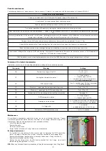
Primary flow rate limitation
(*) The correspondence between valve position and flow rate is indicative. Graphs obtained with pressure head upstream of the HIU = 50 kPa.
N.B. Any limitation must be assessed in accordance with the effective thermal characteristics of the residential unit served.
Anti-legionella function
Primary flow rate limitation in heating mode
DEFAULT SETTING: no limitation (technical parameter t03 =
100)
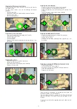
During start-up of the heating cycle from cold, e.g. on changeover
from night-time ambient set point to the daytime set point, the HIU
may demand a significantly higher primary flow rate than the design
one, because of the low temperatures of the secondary medium. This
effect is far greater with high temperature systems in which, during the
transient to the design operating condition, high thermal power values
may be transferred from the primary circuit to the secondary circuit.
This effect can be restricted by lengthening the transient, setting a limit
on the maximum primary flow rate that can be withdrawn in heating
mode.
The flow rate limitation is imposed by controlling the maximum
opening of the primary circuit modulating valve. Since latter is
controlled by a differential pressure limiter, it is possible to supply
direct correspondence between the opening position of the valve and
the circulating flow rate (*)
Primary flow rate limitation in DHW mode
DEFAULT SETTING: no limitation (technical parameter t04 =
100)
Likewise, you can establish a limit to the primary flow rate that can be
tapped for instantaneous DHW production.
The flow rate limitation is imposed by controlling the maximum
opening of the primary circuit modulating valve. Since latter is
controlled by a differential pressure limiter, it is possible to supply
direct correspondence between the opening position of the valve and
the circulating flow rate (*)
A maximum degree of opening (%) can be set via technical menu
parameter t03.
A maximum degree of opening (%) can be set via technical menu
parameter t04.
Max opening (%)
Fl
o
w
r
a
te
(
l/
h)
70
60
50
80
100
90
0
200
400
600
800
1000
1200
Max opening (%)
Fl
o
w
r
a
te
(
l/
h)
70
60
50
80
100
90
0
200
400
600
800
1000
1200
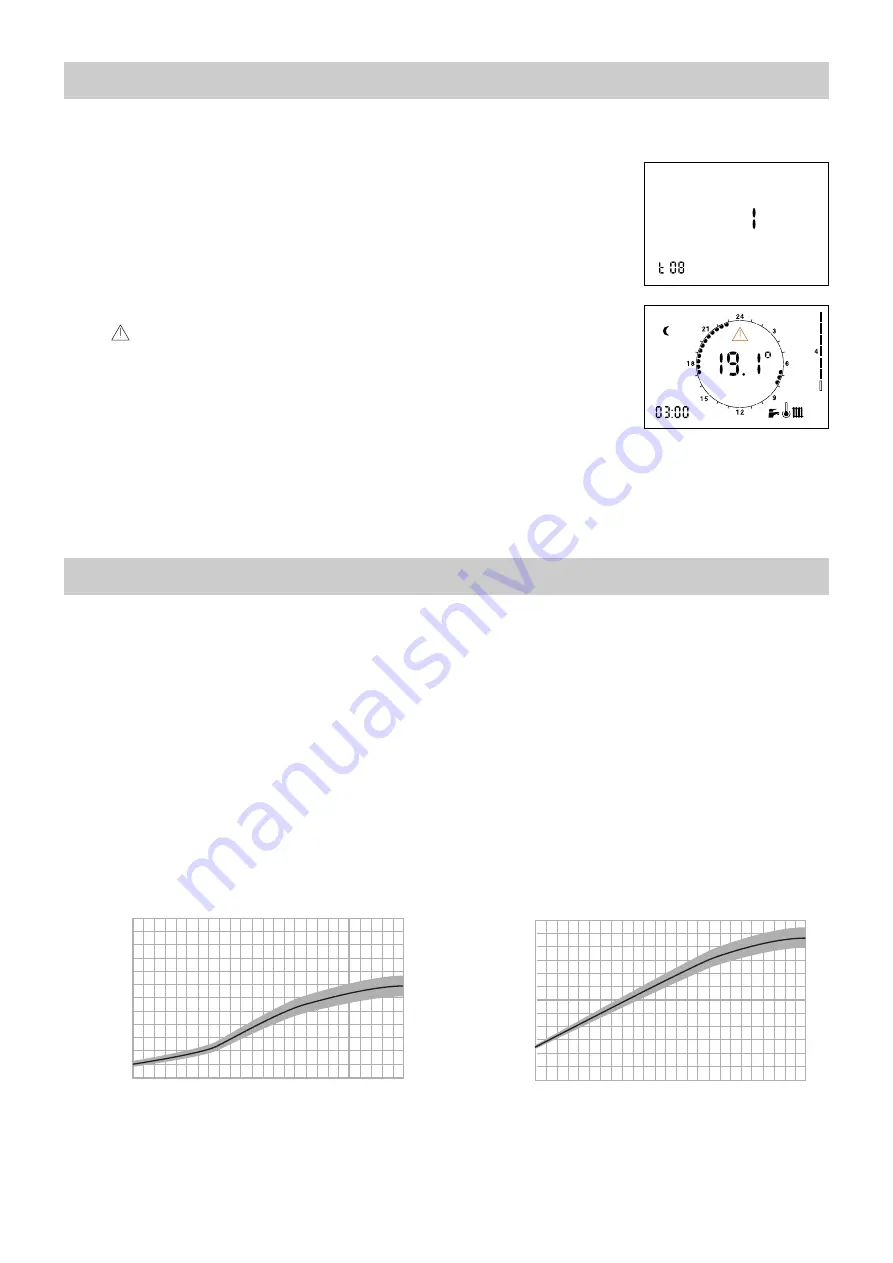
DEFAULT SETTING: anti-legionella function OFF
(technical parameter t08 = 0)
Enabling the anti-legionella function by means of technical parameter
t08 = 1, in time band 3:00 - 3:30:
- the DHW set point will be temporarily increased to the maximum
value (60°C) - the comfort/recirculation function will be forced ON.
As a result of the temperature rise of the set point, at time 3:00 a
comfort function (either pre-heating or recirculation) will be triggered,
bringing the temperature to a value close to 60°C, such as to rapidly
reduce the presence of any bacteria.
During execution of the cycle, the user interface display will show the
blinking
symbol (refer to the adjacent figure).
IMPORTANT!
- Any DHW production that occurs during the time band (3:00 -
3:30) will be at 60°C.
- The cycle execution time band (3:00 - 3:30) is established in
accordance with the time set on the remote control unit.
Incorrect time setting will result in execution of the anti-
legionella function in a different actual time band.
Due to the effect of exchanger thermal inertia, temporary DHW
production at high temperature could proceed also beyond the
time of 3:30.
If the function is enabled thermostatic mixing valves should be
installed on the users level (washbasin/shower, etc.).


