


Circulator - Curves and setting
15
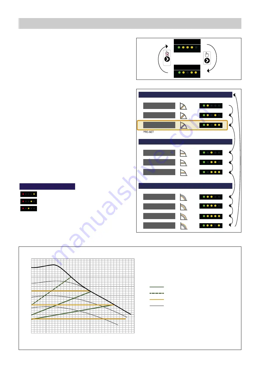
PERFORMANCE
2 s.
SELECTED SETTING
CURVE TYPE
PROPORTIONAL
PROPORTIONAL
PROPORTIONAL
CONSTANT
FIXED SPEED
FIXED SPEED
FIXED SPEED
FIXED SPEED
CONSTANT
CONSTANT
LED SEQUENCE
CURVE TYPE
LED SEQUENCE
CURVE TYPE
LED SEQUENCE
6
H (m w.g.)
G (m
3
/h)
p (bar)
3
0,6
0,4
0,3
0,2
0,1
0
2,5
2
1,5
0,5
0,5
3,5
3
1
6
4
3
2
1
5
7
0,7
0,8
8
Constant head
Proportional head
Constant speed
Factory setting
ALARM STATUS
Blocked
Supply voltage low
Electrical error
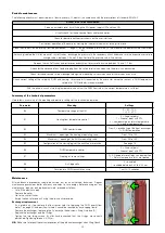
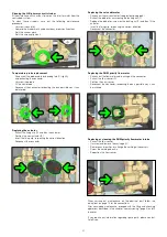
The HIU is equipped with a Grundfos circulator model UPM3 AUTO-L
15-70.
By default, the circulator setting is with the maximum proportional
head characteristic.
Pressing the front key briefly produces the sequence of LEDs
corresponding
to
the
selected
hydraulic
characteristic.
A couple of seconds after pressing the key, the circulator again
produces a sequence of LEDs showing the instantaneous power
consumption:
- 1 yellow LED lit: power between 0 and 25% of Pmax;
- 2 yellow LEDs lit: power between 25 and 50% of Pmax;
- 3 yellow LEDs lit: power between 50 and 75% of Pmax;
- 4 yellow LEDs lit: power between 75 and 100% of Pmax.
To change the characteristic, hold down the front key for more than
two seconds and then press the same key repeatedly until reaching
the required characteristic (refer to the adjacent figure).
Having identified the required characteristic (head - flow rate chart
shown below) wait for about ten seconds for the setting to be
accepted by the circulator, which will then revert to the sequence of
LEDs showing power consumption.
A long press of the front key (>10 s) locks the pump setting,
preventing possible incorrect modifications of the curve.
Unlocking can be done in the same way, with a long press (>10 s) of
the front key.
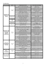
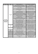
The pump also has a self-diagnostics system to reveal any possible
operating problems.
Any problem detected is shown by a sequence of LEDs:


