background image

WARNINGS
These instructions must be read and understood before installing and servicing the device.
IMPORTANT! FAILURE TO FOLLOW THESE INSTRUCTIONS COULD RESULT IN A SAFETY HAZARD!

1   The  device  must  be  installed,  commissioned  and  serviced  by  qualified  technical  personnel  in  accordance with  national  regulations  and/or  relevant  local

requirements. 

2   If the device is not installed, commissioned and serviced correctly in accordance with the instructions provided in this manual, it may not work properly and may

endanger the user.

3   Clean the pipes of any particles, rust, incrustations, limescale, welding slag and any other contaminants. The hydraulic circuit must be clean. 
4   Make sure that all connection fittings are watertight.
5   When connecting water pipes, take care not to subject the threads to excessive mechanical stress. Over time this could result in breakage, with water leaks causing

damage and/or injury.

6   Water temperatures higher than 50°C may cause severe burns. When installing, commissioning and servicing the device, take the necessary precautions so that

these temperatures will not be hazardous for people.

7   In the case of particularly hard or impure water, the device must be fitted for filtering and treating the water before it enters the device, in accordance with current

legislation. Otherwise the device may be damaged and will not work properly.

8   Any use of the device other than its intended use is prohibited.
9   Any combination of the device with other system components must be made while taking the operational characteristics of both units into consideration.
10 An combination coupling could compromise the operation of the device and/or system.

IMPORTANT

: Risk of electric shock. Live parts. Shut off the electric supply before opening the device enclosure.

1   During installation and maintenance operations, always avoid direct contact with live or potentially hazardous parts.
2   The device must not be exposed to dripping water or humidity, direct sunlight, the weather, heat sources or high intensity electromagnetic fields. This device cannot

be used in areas at risk of explosion or fire.

3   The device must be connected to an independent two-pole switch. If work must be carried out on the device, cut off the electric supply first. Do not use devices

with automatic or time reset, or which may be reset accidentally.

4   Use suitable automatic protection devices in accordance with the electrical characteristics of the region in which the device is installed and in compliance with

current legislation.

5   The device must always be earthed before it is connected to the electric supply. If the device must be removed, always disconnect the earth connection after

disconnecting the electric supply conductors. Check that the earth connection has been made to the highest of standards under applicable legislation.

6   Electrical installation must only be carried out by a qualified technician, in accordance with legal requirements.
7   The appliance does not contain asbestos or mercury.
8   The device is not designed for use by persons of reduced mental, physical or sensory capacity (including children) or persons lacking experience, unless they are

supervised or instructed in use of the device by a person responsible for their personal safety.

LEAVE THIS MANUAL AS A REFERENCE GUIDE FOR THE USER. DISPOSE OF THE PRODUCT IN COMPLIANCE WITH CURRENT LEGISLATION
THE MANUFACTURER RESERVES THE RIGHT TO CEASE PRODUCTION AT ANY TIME AND TO MAKE ANY CHANGES DEEMED USEFUL OR NECESSARY
WITHOUT THE OBLIGATION OF PRIOR NOTICE.

SAFETY INSTRUCTIONS

NOTES

:

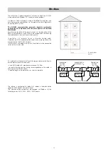
1   Install water hammer arresters to compensate for any overpressure in the domestic water circuit;
2   In  the  presence  of  hot  water  recirculation  or  if  a  check  valve  is  fitted  into  the  domestic  cold  water  inlet,  suitable  devices  must  be  used  to  accommodate  the

expansion of the medium contained within the system and the heat interface unit;

3   All hydraulic connections must be visually checked while pressurising the system. Vibration during transport may cause the connections to become loose. If a fitting

needs to be tightened apply a proper tightening torque, otherwise the components may be damaged by overtightening.

For the updated version of the technical documentation refer to www.caleffi.it.
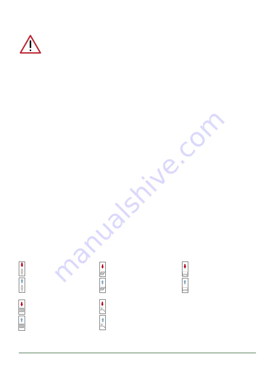
Key to symbols

2

Primary circuit flow

Primary circuit return

D


Low temperature circuit flow

Low temperature circuit return


Medium temperature circuit flow

Medium temperature circuit return

L


Domestic hot water outlet

Domestic cold water inlet

H


High temperature circuit flow

High temperature circuit return

M


Summary of Contents for SATK32 Series

Page 1: ...de 10 Commissioning 9 Electrical installation 8 Hydraulic installation 5 Hydraulic components and diagram 4 Dimensions Technical specifications 3 Safety instructions 2 DHW function Comfort functions P...

Page 2: ...k must be carried out on the device cut off the electric supply first Do not use devices with automatic or time reset or which may be reset accidentally 4 Use suitable automatic protection devices in...

Page 3: ...nimum flow rate to activate domestic water flow meter 2 l min 0 3 Electric supply 230 V ac 10 50Hz Max power consumption 80 W Protection class IP 40 Pump UPM3 15 70 Actuators 24 V stepper motor Probes...

Page 4: ...be 10 Pressure gauge 11 Safety thermostat 12 130 mm heat meter template 13 1 4 F pressure test port 14 Connection for M10x1 heat meter return probe 15 Primary drain cock 16 Connection for M10x1 heat m...

Page 5: ...kflow preventer code 572120 proceed as follows remove the nuts shown in the figure with letter A Hydraulic installation Preliminary operations installation without template After having established th...

Page 6: ...tem in order to remove any residue or impurities that could endanger correct operation of the HIU In order to facilitate these operations a manual bypass flushing valve is available code 789110 N B In...

Page 7: ...pipe To tighten the nuts apply maximum tightening torque of 25 Nm taking account of the indications of the heat meter manufacturer install the flow probe in the M10 pocket B Please refer to the heat m...

Page 8: ...directed toward the exterior of the HIU using the pathways provided in the insulation and on the frame All the low voltage lines must be routed through a single dedicated cable raceway using the path...

Page 9: ...necessary restore the pre charge value shown in the technical specifications Filling the user system SATK32 series HIU can be fitted with a charging unit equipped with a backflow preventer F check va...

Page 10: ...ng modes OFF DHW only summer mode Heating DHW winter mode Heating only Selecting set points current time and comfort function Press the set key repeatedly to set the current time set point temperature...

Page 11: ...arious parameters which can then be edited pressing and rotating knob R Technical parameter t00 Primary limit set return temperature in heating mode Primary limit set return temperature in DHW mode Co...

Page 12: ...ng To set the flow temperature press the SET key until the symbol in the red circle appears for the return temperature limit press the key until the symbols in the green circle are displayed Use the R...

Page 13: ...7 1 freezes the operating set points to prevent inadvertent modifications by the user The comfort function can be alternatively preheating of the DHW plate heat exchanger or management of DHW recircul...

Page 14: ...posed by controlling the maximum opening of the primary circuit modulating valve Since latter is controlled by a differential pressure limiter it is possible to supply direct correspondence between th...

Page 15: ...es a sequence of LEDs showing the instantaneous power consumption 1 yellow LED lit power between 0 and 25 of Pmax 2 yellow LEDs lit power between 25 and 50 of Pmax 3 yellow LEDs lit power between 50 a...

Page 16: ...must be set to 1 2 4 7 This value t05 7 is set by default example 2 Distinction of consumption for DHW production from total consumption in combination with heat meter equipped with dedicated function...

Page 17: ...ire twisted cable Compliance with this requirement becomes even more significant the more extensive the RS 485 network If alternatively a shielded wire is used the shield must be connected solely on t...

Page 18: ...nd disabled Any requests to run cycles not associated to the previous one will continue to run normally Heating flow probe fault Error code 5 Domestic hot water probe fault Error code 6 Return probe f...

Page 19: ...o be interfaced with controllers managing the heating and DHW production services by means of pre paid type logic The HIU interprets an open contact as credit available Closing the contact disables th...

Page 20: ...ween 0 9 and 1 2 bar Restore the pressure value if necessary Re open the shut off valves and restore secondary circuit pressure to a value between 1 3 and 1 7 bar Check for the absence of any liquid d...

Page 21: ...tuator see previous paragraph Extract the obturator unscrewing the locking nut F Replace the obturator screw on the locking nut F and then fit the actuator Insert the fixing clip respecting the correc...

Page 22: ...r partly clogged call qualified personnel to have it serviced modulating valve actuator faulty call qualified personnel to have it replaced DHW temperature probe cable inverted with heating probe rest...

Page 23: ...in charge of system electronic regulator not working call qualified personnel to have it replaced primary circuit flow rate insufficient contact person in charge of system centralised system not work...

Page 24: ...s external sensor prepayment auxilliary microswitch Modbus if required been carried out 15 Has the remote user interface been configured for installation on board thermostat function disabled inside t...

Reviews: