


23
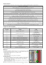
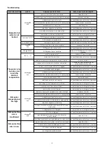
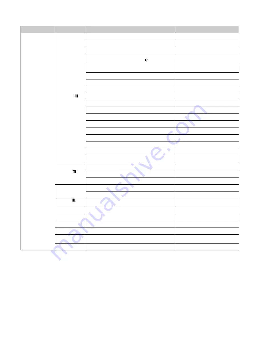
FAULT DESCRIPTION
ALERTS
POSSIBLE CAUSE OF FAULT
OPERATIONS TO BE PERFORMED
The room
does not reach
the desired
temperature
blinking
icon
heating cycle temperature set point too low
increase set point
chrono-thermostat temperature setting incorrect
check programming of chrono-thermostat
HIU strainer clogged
call qualified personnel to have it serviced
primary return temperature limitation intervention (the
following icon appears
)
change the return temperature set
point/disable the function
primary flow rate in heating mode set at an excessively
low limit
change heating valve opening limit
heating valve actuator faulty
call qualified personnel to have it replaced
heating valve obturator blocked
call qualified personnel to have it replaced
modulating valve actuator connector disconnected
reconnect actuator connector
DHW temperature probe cable inverted with heating probe
restore correct connection
presence of air in the system
vent the system
pump not working
call qualified personnel to have it replaced
pump cable not connected
restore connection
possible system shut-off valves/terminals closed
open the valves
centralised system temperature insufficient
contact person in charge of system
electronic regulator not working
call qualified personnel to have it replaced
primary circuit flow rate insufficient
contact person in charge of system
centralised system not working
contact person in charge of system
thermostat function enabled on the remote user interface
when it should be disabled
contact person in charge of system
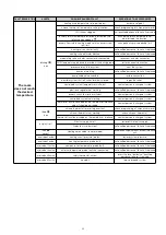
fixed
icon
chrono-thermostat time setting incorrect
check programming of chrono-thermostat
chrono-thermostat not working
check chrono-thermostat
thermostat function disabled on the remote user interface
contact person in charge of system
display is off
Electric supply cut off
restore HIU electric supply
Protection fuse burnt out
call qualified personnel to have it replaced
icon
absent
Heating not enabled (summer mode)
enable heating by means of heat interface
unit
error code 4 active
heating circuit pressure too low
restore system pressure
error code 5 active
heating temperature probe faulty
call qualified personnel to have it replaced
error code 15 active
compensation temperature probe faulty
call qualified personnel to have it replaced
error code 38 active
external temperature probe faulty/not connected
call qualified personnel to have it replaced
error code 69 active
safety thermostat cut-out
press the reset button/call qualified
personnel to have it serviced
error code 80 active
no credit
top-up prepaid system


