


5
Notes for the installer
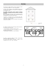
The SATK series HIU is designed for installation in a sheltered domestic environment (or similar), therefore it cannot be installed or used outdoors,
i.e. in areas directly exposed to the weather. Outdoor installation may cause malfunctioning and hazards.
If the appliance is enclosed inside or between cabinets, sufficient space must be provided for routine maintenance procedures. It is recommended
NOT to place electrical devices underneath the HIU, as they may be damaged in the event of safety relief valve activation if not connected to a
discharge tundish, or in the event of leaks occurring at the hydraulic fittings. If this advice is not heeded, the manufacturer cannot be held responsible
for any resulting damage.
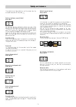
In the event of a malfunction, fault or incorrect operation, the appliance should be deactivated; contact a qualified technician for assistance.
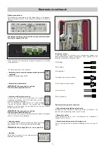
Hydraulic connections - reversibility
Installation of the SATK32 series heat interface unit is reversible (top-down). Installation in the two positions is possible with or without template code
789023.
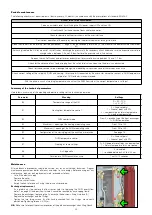
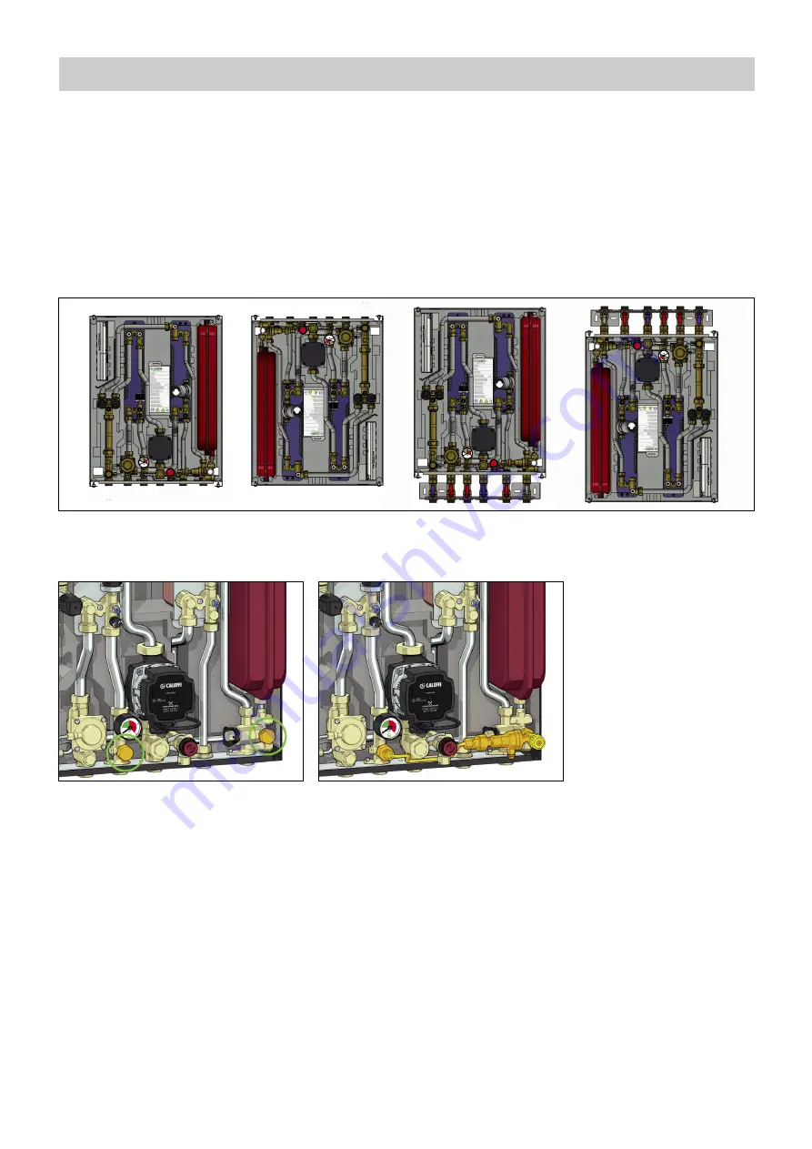
Charging unit
To install the charging unit with backflow preventer code 572120, proceed as follows:
- remove the nuts shown in the figure with letter “A”;
Hydraulic installation
Preliminary operations - installation without template
After having established the point of installation of the appliance, perform the following operations:
· Mark the holes required for the bracket to secure the HIU to the wall
· Mark the position of the hydraulic connections
Check the measurements again and, based on the above connection diagram and the dimensions shown on page 3, proceed with the installation
of the following lines:
• Hydraulic:
1. connection to the central system line
2. heating circuit connection
3. domestic water circuit connection
4. conveyance of safety relief valve and charging unit backflow preventer discharge
NOTE:
We recommend installing manual shut-off valves, especially on the connections to the primary line, thus allowing any necessary maintenance work
to be carried out without having to empty the centralised system.
Before installation, it is recommended to carry out accurate flushing of all the pipes of the system in order to remove any residue or impurities that
could endanger correct operation of the HIU.
In order to facilitate these operations a manual bypass flushing valve is available (code 789110).
- Insert the charging unit as shown in the figure, using the supplied seals.
A
A


