background image

8

Electrical installation

1

2

3

4

5

6

7

8

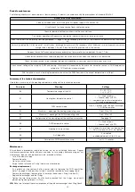
Connection to the electric supply

The  appliance  is  supplied  with  an  electric  supply  cable  which  is  not
fitted with a plug.
The appliance should be electrically connected to a 230 V (ac) single-
phase  +  earth  mains  supply  using  the  three-wire  cable  marked  with
the  label  as  specified  aside,  observing  the  LIVE  (L)  -  NEUTRAL  (N)
polarities and the earth connection. This line must be connected to a
circuit breaker device.
To  extend  the  cable  if  necessary,  use  a  flexible  cable  suitable  for
kitchen  and  heating  appliances  and  for  home,  kitchen  and  office
installations, also in humid environments subject to medium levels of
mechanical  stress  (e.g.  H05V2V2-F:  Uo/U  300/500 V).  Cable
minimum cross-section 3 x 0,75 mm

2

.

Make  sure  that  the  electrical  system  can  withstand  the  maximum
power consumption of the appliance, with particular emphasis on the
cross-section of the wires.
If  you  have  any  doubts,  contact  a  qualified  technician  to  request  a
thorough check of the electrical system.
Electrical safety of the appliance is only achieved when it is correctly
connected to an effective earthing system, constructed as specified in
current safety regulations. This is a compulsory safety requirement. 
Observe  the  applicable  regulations  in  force  in  the  country  of
installation.
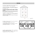
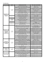
Use the cable pathway provided, as shown in figure 1.

Optional electric connections

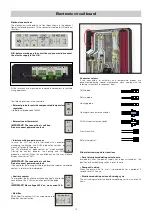
The  controller  has  a  door  on  the  front  providing  access  to  terminal
boards  for  optional  wiring  (see  chapter  “circuit  board  details”).  The
connections in question are all low voltage or potential-free. Any wiring
must be directed toward the exterior of the HIU, using the pathways
provided in the insulation and on the frame. All the low voltage lines
must be routed through a single dedicated cable raceway, using the
pathway that is not used for the electric supply cable (see figure 2), so
that they are separate from the 230 V electric cables.
Any  other  high  voltage  connection,  e.g.  the  one  from  the  auxilliary
microswitch (see pages 13 and 16) must pass through the same cable
pathway used for the main electric supply.

Remote user interface connection

The  HIU  user  interface  has  the  dual  function  of  control  device  and
room thermostat. The remote user interface can be installed on board
the  HIU  or  in  the  room  in  a  position  where  the  temperature
measurements will be of significance for control of the heating function
(in  a  heated  room  in  a  position  where  the  temperature  read  by  the
thermostat is not affected by any nearby heat sources).

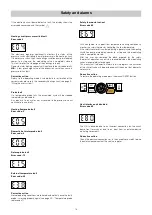
Installation on board the HIU

If  the  remote  user  interface  is  fitted  in  the  dedicated  location  on  the
cover  of  the  HIU,  the  thermostat  function  must  be  disabled  (in  this
case an external thermostat must be used, as described in the next
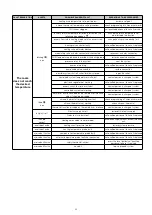
section). The adjacent figures show how to install the remote control
unit:
- Feed the cable from the regulator through the hole in the cover (3);
- Feed  the  cable  from  the  regulator  through  the  rear  of  the  interface

(4);

- Connect  the  two  wires  to  the  terminals  on  the  electronic  circuit

board (the cable is not polarised) (5);

- Close the interface and position it in its housing on the cover (6), (7);
- If necessary, secure the interface from inside the cover by means of

the supplied pair of self tapping screws, spacers, and washers;

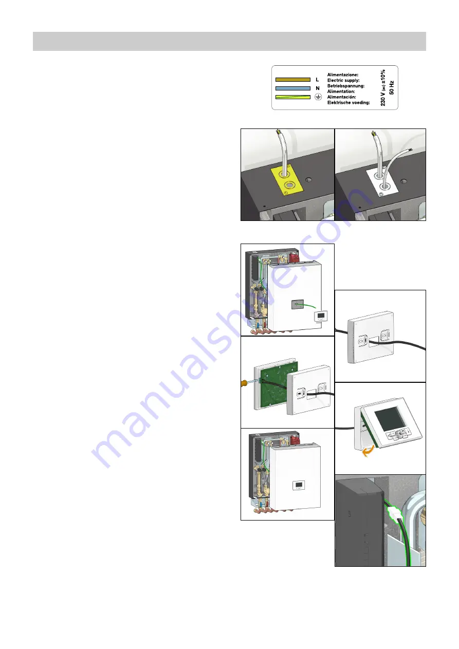
- Plug in the connector (8).

The  thermostat  function  is  enabled  by  default  (refer  to  the
remote control user manual for disabling it).

Summary of Contents for SATK32 Series

Page 1: ...de 10 Commissioning 9 Electrical installation 8 Hydraulic installation 5 Hydraulic components and diagram 4 Dimensions Technical specifications 3 Safety instructions 2 DHW function Comfort functions P...

Page 2: ...k must be carried out on the device cut off the electric supply first Do not use devices with automatic or time reset or which may be reset accidentally 4 Use suitable automatic protection devices in...

Page 3: ...nimum flow rate to activate domestic water flow meter 2 l min 0 3 Electric supply 230 V ac 10 50Hz Max power consumption 80 W Protection class IP 40 Pump UPM3 15 70 Actuators 24 V stepper motor Probes...

Page 4: ...be 10 Pressure gauge 11 Safety thermostat 12 130 mm heat meter template 13 1 4 F pressure test port 14 Connection for M10x1 heat meter return probe 15 Primary drain cock 16 Connection for M10x1 heat m...

Page 5: ...kflow preventer code 572120 proceed as follows remove the nuts shown in the figure with letter A Hydraulic installation Preliminary operations installation without template After having established th...

Page 6: ...tem in order to remove any residue or impurities that could endanger correct operation of the HIU In order to facilitate these operations a manual bypass flushing valve is available code 789110 N B In...

Page 7: ...pipe To tighten the nuts apply maximum tightening torque of 25 Nm taking account of the indications of the heat meter manufacturer install the flow probe in the M10 pocket B Please refer to the heat m...

Page 8: ...directed toward the exterior of the HIU using the pathways provided in the insulation and on the frame All the low voltage lines must be routed through a single dedicated cable raceway using the path...

Page 9: ...necessary restore the pre charge value shown in the technical specifications Filling the user system SATK32 series HIU can be fitted with a charging unit equipped with a backflow preventer F check va...

Page 10: ...ng modes OFF DHW only summer mode Heating DHW winter mode Heating only Selecting set points current time and comfort function Press the set key repeatedly to set the current time set point temperature...

Page 11: ...arious parameters which can then be edited pressing and rotating knob R Technical parameter t00 Primary limit set return temperature in heating mode Primary limit set return temperature in DHW mode Co...

Page 12: ...ng To set the flow temperature press the SET key until the symbol in the red circle appears for the return temperature limit press the key until the symbols in the green circle are displayed Use the R...

Page 13: ...7 1 freezes the operating set points to prevent inadvertent modifications by the user The comfort function can be alternatively preheating of the DHW plate heat exchanger or management of DHW recircul...

Page 14: ...posed by controlling the maximum opening of the primary circuit modulating valve Since latter is controlled by a differential pressure limiter it is possible to supply direct correspondence between th...

Page 15: ...es a sequence of LEDs showing the instantaneous power consumption 1 yellow LED lit power between 0 and 25 of Pmax 2 yellow LEDs lit power between 25 and 50 of Pmax 3 yellow LEDs lit power between 50 a...

Page 16: ...must be set to 1 2 4 7 This value t05 7 is set by default example 2 Distinction of consumption for DHW production from total consumption in combination with heat meter equipped with dedicated function...

Page 17: ...ire twisted cable Compliance with this requirement becomes even more significant the more extensive the RS 485 network If alternatively a shielded wire is used the shield must be connected solely on t...

Page 18: ...nd disabled Any requests to run cycles not associated to the previous one will continue to run normally Heating flow probe fault Error code 5 Domestic hot water probe fault Error code 6 Return probe f...

Page 19: ...o be interfaced with controllers managing the heating and DHW production services by means of pre paid type logic The HIU interprets an open contact as credit available Closing the contact disables th...

Page 20: ...ween 0 9 and 1 2 bar Restore the pressure value if necessary Re open the shut off valves and restore secondary circuit pressure to a value between 1 3 and 1 7 bar Check for the absence of any liquid d...

Page 21: ...tuator see previous paragraph Extract the obturator unscrewing the locking nut F Replace the obturator screw on the locking nut F and then fit the actuator Insert the fixing clip respecting the correc...

Page 22: ...r partly clogged call qualified personnel to have it serviced modulating valve actuator faulty call qualified personnel to have it replaced DHW temperature probe cable inverted with heating probe rest...

Page 23: ...in charge of system electronic regulator not working call qualified personnel to have it replaced primary circuit flow rate insufficient contact person in charge of system centralised system not work...

Page 24: ...s external sensor prepayment auxilliary microswitch Modbus if required been carried out 15 Has the remote user interface been configured for installation on board thermostat function disabled inside t...

Reviews: