


4
3
9
4
7
10
8
5
2
1
20
11
14
19
18
17
13
12
22
23
24
16
27
25
26
21
6
15
29
28
TS
P
TA
2
V
V
V
V
V
V
3
4
5
6
7
8
9
10
11
12
13
14
15
18
17
16
20
19
23
24
25
26
27
28
29
21
22
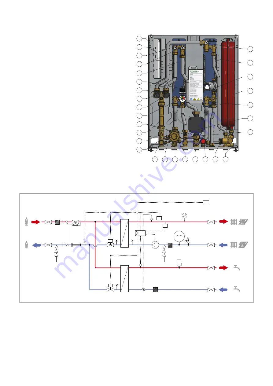
1. Frame
2. Controller
3. Heating exchanger primary circuit air venting/drain
4. Heating exchanger secondary circuit air venting/drain
5. Heating exchanger
6. Pressure switch
7. 2-way modulating valve - Heating
8. 2-way modulating valve - DHW
9. Return temperature probe
10. Pressure gauge
11. Safety thermostat
12. 130 mm heat meter template
13. 1/4” F pressure test port
14. Connection for M10x1 heat meter return probe
15. Primary drain cock
16. Connection for M10x1 heat meter flow probe
17. Mesh st 1/4” F pressure test port
18. Differential pressure regulating valve
19. Secondary drain cock + mesh strainer
20. Safety relief valve
21. Flow meter (t sensor)
22. Mesh strainer
23. Heating flow temperature probe
24. Pump
25. DHW temperature probe
26. Expansion vessel
27. Water hammer arrester
28. DHW exchanger
29. DHW exchanger primary circuit air venting/drain
Characteristic components
Hydraulic diagram


