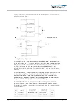
Depending on the reason of the motor stop a motor reset command may be neccessary to
release the axis from this state.
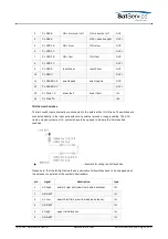
pin
signal
DUAL-START
DIR-START
type
1
EL FWD E
ON = motor on / right
ON = motor on
OUT-
2
EL FWD C
OFF = motor off
OUT+
3
EL REV E
ON = motor on / left
ON = direction left
OUT-
4
EL REV C
OFF = direction right
OUT+
5
EL SPD1 E
ON = slow
ON = slow
OUT-
6
EL SPD1 C
OUT+
7
EL SPD2 E
ON = fast
ON = fast
OUT-
8
EL SPD2 C
OUT+
9
EL RES E
reset driver
reset driver
OUT-
10
EL RES C
OUT+
11
EL RESERV E
axis stopped
axis stopped
OUT-
12
EL RESERV C
OUT+
13
EL FAULT K
driver fault
driver fault
IN-
14
EL FAULT A
IN+
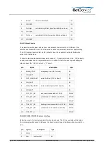
CON14 GND-EXT Distribution
CON12 provides eight clamps to the GND-EXT rail. It has been included to simplify the external
cabling.
pin
signal
description
type
1
GND EXT
2
GND EXT
3
GND EXT
4
GND EXT
5
GND EXT
6
GND EXT
7
GND EXT
8
GND EXT
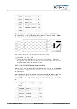
CON15 Polarization Motor Driver
All signals for motor control are provided as free floating opto coupler inputs / outputs. This gives
a maximum of flexibility to adapt the cabling to the motor driver units. They probably will combine
(C) 2022, SatService GmbH
www.satnms.com
ACU-ODM-UM-2209 Page 16/73


