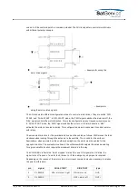
3
PL REV E
ON = motor on / left
ON = direction left
OUT-
4
PL REV C
OFF = direction right
OUT+
5
PL SPD1 E
ON = slow
ON = slow
OUT-
6
PL SPD1 C
OUT+
7
PL SPD2 E
ON = fast
ON = fast
OUT-
8
PL SPD2 C
OUT+
9
PL RES E
reset driver
reset driver
OUT-
10
PL RES C
OUT+
11
PL RESERV E
axis stopped
axis stopped
OUT-
12
PL RESERV C
OUT+
13
PL FAULT K
driver fault
driver fault
IN-
14
PL FAULT A
IN+
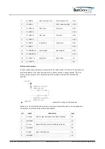
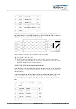
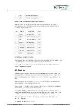
CON16 Limit Switches
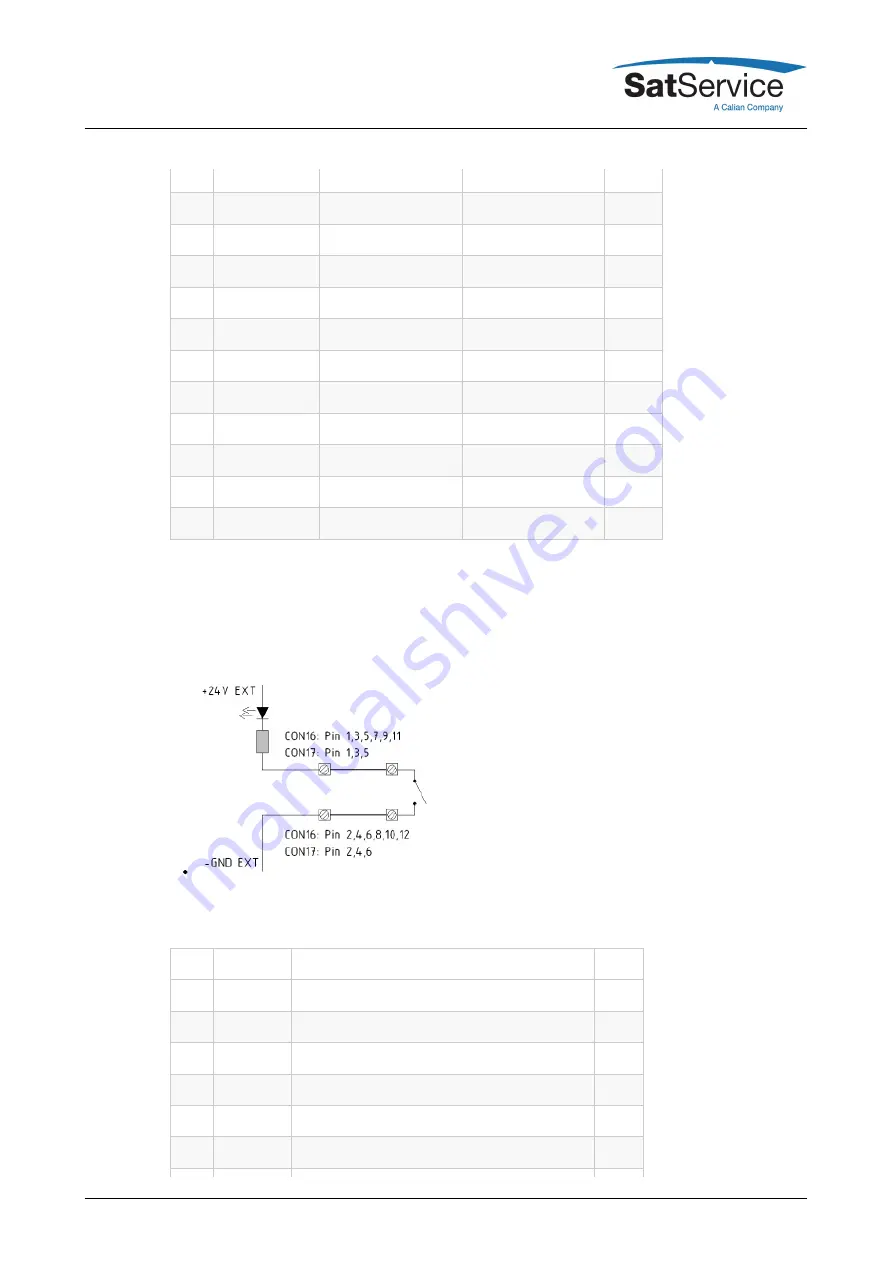
The limit switch inputs internally are connected to the external 24V / GND rails. The switches are
connected directly to the input pairs without any external ground or supply cabling. The ACU
treats a closed contact as OK, contacts have to be opened to indicate the 'limit reached'
condition.
--- Example for wiring the limit switches
Please note, that the left/right azimuth and polarization limit switches have to be swapped when
the antenna is operated at the southern hemisphere.
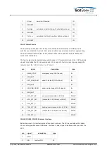
pin
signal
description
type
1
AZ High
azimuth right limit (view from behind antenna)
IN
2
GND EXT
IN
3
AZ Low
azimuth left limit (view from behind antenna)
IN
4
GND EXT
IN
5
El High
upper limit Elevation
IN
6
GND EXT
IN
(C) 2022, SatService GmbH
www.satnms.com
ACU-ODM-UM-2209 Page 18/73


