7
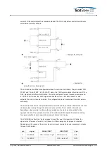
+5V
encoder power supply
8
+24V
encoder power supply
CON18, CON19, CON20 Analog Angle Sensor Interface
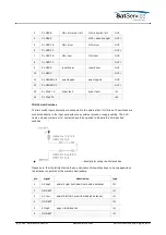
Below the pinout of an analog type positional sensor interface board is shown. The ACU is
available with resolver, SSI or analog position sensor interfaces. You have to select type of
interface when you order the ACU.
pin
signal
description
type
1
AGND
analog ground
OUT
2
INPUT
A/D converter input
IN
3
REF
reference voltage
OUT
4
AGND
analog ground
OUT
5
+15V (opt)
optional DC out
OUT
6
-15V (opt)
optional DC out
OUT
7
+9V (opt)
optional DC out
OUT
8
GND
digital ground
OUT
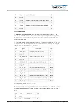
The ACU uses opto coupler interfaces to the motor drivers, limit switches etc. This permits to use
a complete separate power supply with a separate ground for these circuits.
To simplify the cabling of these circuits, the ACU distributes the external 24V and GND lines
through a separate set of clamps.
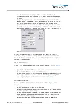
This chapter describes how to install and start-up the sat-nms ACU-ODM. It is a step-by-step
description without detailed description. If you need more detailed description for e.g. some
parameter settings, please refer to chapter
5 Operation
, all of the parameters are described
here.
Before you start, please first read the
Safety Instructions
chapter. It contains some important
recommendations to prevent damage from the ACU.
Then, we strongly recommend to do a first setup of the ACU on a lab desk before installing it at
it's final location. This is mainly for the following reason:
To setup the ACU's IP parameters, the PC used for configuring and the ACU must either be
connected to the same Ethernet hub or must be connected directly with a crossover cable. The
initialization program does not work through routers or intelligent network switches.
Hence, the typical sequence of tasks when putting an sat-nms ACU outdoor module into
operation is as follows:
1. Read the chapter
Safety Instructions
.
(C) 2022, SatService GmbH
www.satnms.com
ACU-ODM-UM-2209 Page 21/73


