the 'Target' page where you can store and recall the antenna pointing for up to eight
satellites.
Tracking
: sat-nms ACUs with the tracking option installed offer the tracking mode
and tracking fine tune parameters on this page.
Test
: By clicking to this button you switch to
the 'Test' page. The 'Test' page shows the low level I/O signals of the ACU. It helps you to
install the ACU or to identify a malfunction of peripheral components.
Setup
: This button
switches to the 'Setup' page which lets you inspect or change less common parameters
which usually are set only once to adapt the ACU to it's working environment.
Info
: After a
mouse click to this button, the ACU outdoor module shows a table with information like the
serial number of the device or the revision ID and compilation date of the software.
Help
:
Clicking to this button shows the on-line version of this user manualStep Move: Clicking to
the buttons in this area moves the antenna a small step to the indicated direction. For
azimuth and elevation 'small step' and 'large step' buttons are provided. A 'small step' is the
angle defined with the 'XX step delta' parameters at the
Setup
page, a 'large step' is ten
times this value. With the polarization axis, steps always are 1°.STOP: Clicking to the STOP
button immediately stops all motors. The ACU indicates a fault. A click to the RESET button
releases this fault.RESET: The RESET button lets the ACU acknowledge any motor diver
faults by activating the reset-circuit to the motor drivers for 800 msec. All faults internally
latched by the ACU are cleared and the target pointing values are set to the values actually
read from the position sensors.STANDBY: The STANDBY button puts the pointing loop of all
axes to 'standby' mode: Differences between measured and commanded value do not cause
the motors to be driven in this mode. Standby mode can be used for maintenance purposes
or to move the antenne by actuating the frequency inverters directly by hardware circuits. To
leave standby mode, click the STANDBY button again or RESET.
The 'Pointing' page is the main page of the ACU user interface which shows the actual antenna
pointing and some status information. The 'Pointing' page automatically refreshes once a second.
The refresh-rate may be adjusted on the setup-page from software version 2.1.007 or higher.
The table below describes the information shown by this page:
Parameter Name --- Description
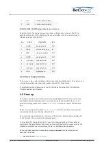
Azimuth Elevation Polarization --- The bold printed figures show the actual antenna pointing
angles as read from the position sensors. If the polarization axis is not controlled by the ACU,
'-.---°' is displayed in the polarization field.
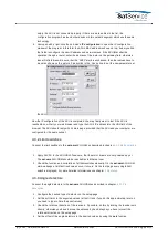
Xx. target value --- Below the measured angles the ACU displays the target values of the
antenna pointing. The target values are the angles which have been commanded to the
ACU. You may click to a target angle in order to change the pointing manually. The ACU
display a dialog page where you can enter the new pointing angle. If you click to the
'SUBMIT' button in this dialog page, the antenna immediately moves to the new position. To
go back to the main page without changing the pointing, click to the 'Back' button of your
Web browser.
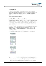
Axis state flags --- Below the target values, for each axis there is a field reserved which
contains some state information for this axis. While the motor is running, 'MOVING' is
displayed at this place. If the motor has been stopped due to a fault or an emergency stop
request, a red label 'STOPPED' is displayed. Finally, if the ACU recognizes the activation of a
limit switch, the orange colored label 'LIMIT' is displayed in this field. If the ACU is in standby
mode, 'STANDBY' ist displayed for all axes.
(C) 2022, SatService GmbH
www.satnms.com
ACU-ODM-UM-2209 Page 27/73


