background image

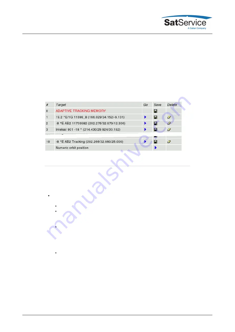
The first target location, labeled 'adaptive tracking memory', is reserved for special purposes: If
you store to this target location, this saves the tracking parameters and the tracking memory as
well. When this memory location is recalled later on, the parameters and the memory contents
are restored. This may be useful to track another satellite for a couple of hours and then to
return to the first satellite. If the tracking memory has been saved before the antenna has been
moved to the second satellite, it may be restored after the antenna returned to the old position.

You should not use the first target location for general purposes in order to keep it available for
the short time storage described above.

Targets Page Example:

5.4 Tracking Parameters

sat-nms ACUs with the tracking function installed give access to the tracking mode and the fine
tune parameter which lets you adapt the tracking to the individual requirements of the antenna
and the satellite you are tracking to. ACUs without tracking function show an empty page at this
place.

Trackingmode --- The tracking mode parameter selects the tracking method, the ACU
actually uses. Possible selection are:

OFF --- No tracking is performed.
STEP --- Step track mode. In regular intervals, the antenna performs small search steps
to optimize the pointing. Chapter 

'8.3.0 Step Track'

 gives more information about this

mode.
ADAPTIVE --- The adaptive tracking mode works the same way as step track, but it
additionally is capable to predict the satellite's position when the beacon reception fails.
It computes mathematical models of the satellites motion from the step track results
recorded over a certain time. Details about this tracking mode are given in chapter

'8.4.0 Adaptive Tracking'

 .

PROGRAM --- The program tracking mode is different from the modes above. The ACU
moves the antenna along a path which is described in a data file. No beacon reception
is required for this. You have to create such a data file and copy it with FTP to the ACU
before you can use this mode. SatService GmbH provides a PC software which lets you
easily create data files for program track from commonly used ephemeris data sets for
geostationary satellites. Chapter 

'8.5.0 Program Tracking'

 describes this tracking mode

more detailed.

.ts CLEARMEMORYClicking to this mark clear the tracking memory. You should do this when you
start to track a new satellite. Clearing the tracking memory about half an hour after tracking
started significantly improves the quality of the first adaptive tracking model which will be
evaluated after 6 hours of tracking. This is because the model does not get disturbed by the first

(C) 2022, SatService GmbH

www.satnms.com

ACU-ODM-UM-2209 Page 30/73

Summary of Contents for SatService sat-nms ACU-ODM

Page 1: ...s ACU ODM User Manual Version 5 0 002 Copyright SatService Gesellschaft für Kommunikationssysteme mbH Hardstrasse 9 D 78256 Steisslingen satnms support satservicegmbh de www satnms com www satservicegmbh de Tel 49 7738 99791 10 ...

Page 2: ...b based User Interface 27 5 2 Antenna Pointing 29 5 3 Target Memory 30 5 4 Tracking Parameters 32 5 5 Test Page 34 5 6 Setup 40 5 7 Handheld Terminal 41 6 Frontpanel operation 43 6 1 Display mode 43 6 2 The main menu 44 6 3 Select targets 44 6 4 Set tracking mode 44 6 5 Step move 45 6 6 Jog mode 45 6 7 Standby 45 6 8 Set az el pl by editing Numeric Parameters 46 7 Remote Control 46 7 1 General com...

Page 3: ...s 66 8 4 Adaptive Tracking 67 8 4 1 The sat nms Adaptive Tracking Algorithm 69 8 4 2 The Tracking Memory 70 8 4 3 Adaptive Tracking Parameters 71 8 5 Program Tracking 71 8 5 1 Practical Usage 72 8 5 2 File Format 72 8 6 Faults and Tracking 73 9 Specifications C 2022 SatService GmbH www satnms com ACU ODM UM 2209 Page 2 73 ...

Page 4: ... Of Contents 1 Introduction 2 Safety Instructions 3 The sat nms ACU ODM 4 Installation 4 1 Mechanical installation 4 2 Interfaces to the Antenna Pin descriptions 4 2 1 Connector Layout 4 2 2 Pin descriptions 4 2 3 Power Supply Cabling 4 3 Start up 4 3 1 Setting the IP Address 4 3 2 Limit switches 4 3 3 Angle detectors 4 3 4 Motors 4 3 5 Pointing Tracking 4 3 6 Backup of ACU settings 5 Operation 5 ...

Page 5: ...zation interface The sat nms ACU is available as sat nms ACU ODM only the core module integrated in a compact case prepared for mounting on a 35mm DIN rail sat nms ACU ODU complete antenna controller system for AC or DC Motors integrated in an outdoor cabinet that could be mounted directly to the antenna By mounting a sat nms LBRX beacon receiver into this cabinet you have a complete antenna track...

Page 6: ...www satnms com Safety Instructions This chapter gives an overview about the safety precautions that have to be observed during installation operation and maintenance Unit Overview The installation chapter gives informations about the different modules that are integrated in the ACU not ACU ODM and ACU19 Installation Start up The installation chapter guides through the installation and setup of the...

Page 7: ...ion is prohibited The unit described in this manual is designed to be used by properly trained personnel only Adjustment maintenance and repair of the exposed equipment shall be carried out only by qualified personnel who are aware of hazards involved Refer servicing to qualified personnel To prevent electrical shock do not remove covers For the correct and safe use of the instrument it is essenti...

Page 8: ...oor unit which offers extended tracking capabilities and a full featured visualization interface The ACU ODM is designed as a closed compact module prepared for mounting on a 35mm DIN rail Below the top viw and connector layout of the ACU outdoor module is shown Except the network connector which is a standard 10 Base T Ethernet socket all connectors are Phoenix Contact Combicon plugs clamps Insid...

Page 9: ...ctor Layout Below the connector layout of the ACU outdoor module is shown Except the network connector which is a standard 10 Base T Ethernet socket all connectors are Phoenix Contact mini Combicon plugs clamps which are delivered together with the sat nms ACU ODM Pin 1 of each connector is the rightmost if you look at the screws of the connector and the plugs are directed to you Inside the ACU co...

Page 10: ...o cabling required pin signal description type 1 AUX1 INA IN 2 AUX1 IN K IN 3 AUX2 INA IN 4 AUX2 IN K IN 5 AUX2 INA IN 6 AUX2 IN K IN 7 AUX2 INA IN 8 AUX2 IN K IN CON3 24V EXT Distribution CON3 provides eight clamps to the 24V EXT rail It has been included to simplify the external cabling pin signal description type 1 24V_EXT 2 24V_EXT 3 24V_EXT 4 24V_EXT 5 24V_EXT 6 24V_EXT 7 24V_EXT 8 24V_EXT C ...

Page 11: ...ternal watchdog circuit be aware the in adaptive tracking mode delays of some seconds are possible while the acu calculates the orbital model CON5 Spare Outputs 1 4 CON5 provides another four opto isolated spare outputs for the ACU These inputs are reserved for customized versions of the ACU software they normally are not used There is no cabling required pin signal description type 1 AUX 1 OUT C ...

Page 12: ... does not include the nick roll angles into the displayed antenna pointing pin signal description type 1 9V roll reference output 9VDC OUT 2 VRAT X roll measurement input IN 3 GND roll ground 4 9V nick reference output 9VDC OUT 5 VRAT Y nick measurement input IN 6 GND nick ground CON8 Serial Interfaces The ACU owns two serial interfaces The first is reserved to poll a GPS receiver in order to get ...

Page 13: ...eft to select the RS232 interface JP2 switches between the RS422 4 wire mode and RS485 2 wire mode To select RS485 2 wire mode put the jumper to position 1 2 left Use the TX data lines CON8 Pins 7 8 in this mode JP4 and JP5 activate 100 Ohms termination resistors between the RS422 data lines The lines are terminated if the jumper is set CON9 Power Supply At CON9 the power supply for the ACU itself...

Page 14: ... different configuration modes to control a motor driver They are called DIR START and DUAL START In DIR START mode the FWD signal switches the motor on off the REV signal controls the motor direction This is the configuration many frequency inverters use In DUAL START mode the FWD signal switches the motor on in forward direction REV activates the motor in reverse direction This configuration mod...

Page 15: ...Z SPD1 E ON slow ON slow OUT 6 AZ SPD1 C OUT 7 AZ SPD2 E ON fast ON fast OUT 8 AZ SPD2 C OUT 9 AZ RES E reset driver reset driver OUT 10 AZ RES C OUT 11 AZ RESERV E axis stopped axis stopped OUT 12 AZ RESERV C OUT 13 AZ FAULT K driver fault driver fault IN 14 AZ FAULT A IN CON11 24V EXT Distribution CON11 provides four clamps to the 24V EXT rail It has been included to simplify the external cablin...

Page 16: ...or on off the REV signal controls the motor direction This is the configuration many frequency inverters use In DUAL START mode the FWD signal switches the motor on in forward direction REV activates the motor in reverse direction This configuration mode is convenient to control a motor with relays The movement direction for the azimuth drive must be cabled as follows FWD moves the antenna to the ...

Page 17: ... C OUT 11 EL RESERV E axis stopped axis stopped OUT 12 EL RESERV C OUT 13 EL FAULT K driver fault driver fault IN 14 EL FAULT A IN CON14 GND EXT Distribution CON12 provides eight clamps to the GND EXT rail It has been included to simplify the external cabling pin signal description type 1 GND EXT 2 GND EXT 3 GND EXT 4 GND EXT 5 GND EXT 6 GND EXT 7 GND EXT 8 GND EXT CON15 Polarization Motor Driver ...

Page 18: ...rection for the polarization drive must be cabled as follows FWD moves the feed clockwise when looking through the antenna to the satellite This is valid for the northern hemisphere when operated on the southern hemisphere the motor must be cabled for the opposite direction The evaluation routines in the software which compute the antenna pointing for a given satellite location require the movemen...

Page 19: ...switches are connected directly to the input pairs without any external ground or supply cabling The ACU treats a closed contact as OK contacts have to be opened to indicate the limit reached condition Example for wiring the limit switches Please note that the left right azimuth and polarization limit switches have to be swapped when the antenna is operated at the southern hemisphere pin signal de...

Page 20: ...ack of power supply the relays connect the _NO circuit to the _C circuit pin signal description type 1 EMER_STOP emergency stop OK if closed IN 2 GND_EXT IN 3 ANT_HUB_FAULT alarm hub fault OK if closed IN 4 GND_EXT IN 5 SW_CAB_OPEN alarm cabinet open OK if closed IN 6 GND_EXT IN 7 ACU_FLT_NC acu alarm connected to 9 if OK RELAY 8 ACU_FLT_NO connected to 9 if there is a FAULT RELAY 9 ACU_FLT_C RELA...

Page 21: ...this will introduce a ground loop and cause a significant degradation of the resolver s accuracy CON18 CON19 CON20 SSI Positional Encoder Interface Below the pinout of a SSI type positional encoder interface board is shown The ACU is available with resolver SSI or analog position sensor interfaces You have to select type of interface when you order the ACU The SSI positional encoder may be powered...

Page 22: ...et of clamps 4 3 Start up This chapter describes how to install and start up the sat nms ACU ODM It is a step by step description without detailed description If you need more detailed description for e g some parameter settings please refer to chapter 5 Operation all of the parameters are described here Before you start please first read the Safety Instructions chapter It contains some important ...

Page 23: ...puter The CD ROM shipping with the sat nms ACU ODM Setting the ACU s IP parameters now is easily done within a few minutes 1 First install a network cable between the ACU and your computer If you have a crossover cable available this is very easy simply put the cable into the network connectors of computer and ACU Without a crossover cable you need to connect both the computer and the ACU to the s...

Page 24: ...me subnet 4 3 2 Limit switches Connect the limit switches to the sat nms ACU ODM as described in chapter 4 2 2 Pin description 1 Apply 24V DC to the ACU ODM Take care that the motor drivers are not powered up yet The sat nms ACU ODM should be reachable via Ethernet now 2 Check the function and correlation of all limit switches manually On the sat nms ACU ODM main webpage a limit fault is shown as ...

Page 25: ... Set the soft limits to the desired values e g 1 before the hardware limit switch is activated 4 3 5 Pointing Tracking Now the setup of all interfaces to the antenna is done By this everything is prepared to configure the ACU to the desired operation mode to save targets and finally to set the sat nms ACU ODM into service In chapter 5 Operation you find a detailed description of the pointing and t...

Page 26: ... in the drop down list The file will immediately be copied to the location shown on the left side If you have saved targets you might backup them in the same way They are named targetXX txt XX represents the number of the target 8 To copy a backup file to the ACU browse on the left side if the window to the desired app dat file and copy this file to the ACU in the same way right click copy 9 After...

Page 27: ...of a web page you want to see type in the IP address of the sat nms ACU you want to control The ACU shows a web page consisting of a navigation bar at the left side of the browser window and the actual antenna pointing in the main part of the window The readings automatically refresh once a second The refresh rate may be adjusted on the setup page from software version 2 1 007 or higher The naviga...

Page 28: ...anded value do not cause the motors to be driven in this mode Standby mode can be used for maintenance purposes or to move the antenne by actuating the frequency inverters directly by hardware circuits To leave standby mode click the STANDBY button again or RESET 5 2 Antenna Pointing The Pointing page is the main page of the ACU user interface which shows the actual antenna pointing and some statu...

Page 29: ...isplayed in this field If there is more than one fault at a time the ACU concatenated the fault descriptions More detailed information about faults are available in chapter Faults and Tracking If one axis stops operation due to a fault the step tracking also stopps operation Possible faults are EMERGENCY STOP Someone opened the emergency stop circuit The ACU stopped all motors and stays in this st...

Page 30: ...his dialog the antenna moves to the stored location Save For each memory location the table shows a floppy disk icon in the Save column Clicking to this icon saves the actual pointing and tracking parameters if applicable to the selected memory location Again there is a confirmation dialog page before the data actually is saved Delete Analogous to the Save icon the table shows an eraser icon in th...

Page 31: ...nna performs small search steps to optimize the pointing Chapter 8 3 0 Step Track gives more information about this mode ADAPTIVE The adaptive tracking mode works the same way as step track but it additionally is capable to predict the satellite s position when the beacon reception fails It computes mathematical models of the satellites motion from the step track results recorded over a certain ti...

Page 32: ...probably will require a shorter cycle time very stable satellites can be perfectly tracked with one step track cycle every 15 minutes 900 seconds The maximum cycle time accepted by the ACU is 1638 seconds Measurementdelay During a steptrack cycle the ACU positions the antenna to a certain offset and then measures the level Between the moment when the antenna reached commanded position and the beac...

Page 33: ...amplitudes or the model does not fit at all This may be the case if a satellite gets repositioned in the orbit A typical threshold value is 20 this will detect very early that a model does not fit to describe the satellite s motion If this value causes false alarms too often you may want to raise the threshold to 50 Setting it to 0 switches the threshold monitoring completely off AZMaximummodeltyp...

Page 34: ...s eight times a second for each axis having the motor driver type set to DIR START or DUAL START This immediately will overwrite any change you make If you want to test if the motor driver outputs command the motor driver as expected switch the motor driver type for this axis to NONE at the Setup page before you set the outputs manually The Test page is re read by the Web browser about once a seco...

Page 35: ...page without changing the parameter you edited The table below lists the settings provided by this page General This section of the setup page contains some general setup parameters Parameter Name Description Axes control mode The ACU knows two axes control modes The PARALLEL mode treats the azimuth elevation axes independently If a new pointing is commanded both motors are activated in parallel t...

Page 36: ...erent for the azimuth elevation axes This lets the ACU calculate suitable tracking step sizes individually for each axis Step delta This parameter defines size of a step the antenna moves when you click to the arrow buttons on the ACU main page If you are using the arrow buttons to fine tune the antenna pointing manually the best value is the pointing hysteresis described below This lets you move ...

Page 37: ...ration scale Normally the ACU assumes that the full range of a position sensor corresponds 360 If you are using a multiturn position sensor or if the position sensor is mounted to the shaft of a gear rather than to the antenna axis directly the position sensor reading must be scaled The displayed angle is computed as follows displayed value raw reading pre scale offs scale pos scale offsMathematic...

Page 38: ... the ACU from running the antenna to the limit position under normal conditions Beacon Receiver Parameter Name Description Beacon RX type Selects the source of the beacon level the ACU shall use Available options are SATNMS and VOLTAGE In SATNMS mode the ACU reads the beacon level from a sat nms beacon receiver via UDP in VOLTAGE mode the A D converter input of the ACU is read Please mention that ...

Page 39: ...are version 2 1 007 or higher the sat nms ACU contains an SNMP agent listening at UDP port 161 The SNMP agent provides a common subset of the MIB II system interface parameters and gives full access to the remote control capabilities of the sat nms ACU with a number of MIB objects placed in the private enterprises tree The actual MIB file defining the ACU s private MIB may be downloaded from the A...

Page 40: ... the password for the user login Default password is user When you are logged in as user you can command the antenna pointing set the tracking parameters if applicable and store recall targets You can t modify the setup parameters or issue low level commands on the test page while logged in as user Admin password Here you can define the password for the admin login Default password is admin When y...

Page 41: ...n is not yet available at ACU RMU and ACU19 Version Startup Set parameter RS485 address on the ACUs Setup page to TERM This enables communication between the ACU and the sat nms handheld Connect the Handheld with the provided cable Handheld 9pol DSUB Power supply ACU C 2022 SatService GmbH www satnms com ACU ODM UM 2209 Page 40 73 ...

Page 42: ...size small steps x keypress x is the value that was set on the setup screen large steps 10 x keypress continuous mode the antenna moves as long until the button is pushed or a limit switch or limit value is reached Turns the polarisation clockwise Moves the antenna up EL Moves the antenna to the left AZ Stops the antenna movement only in continuous mode Moves the antenna to the right AZ Moves the ...

Page 43: ...keys named ENTER and CLEAR Some keys have a second meaning The first meaning of the keys remains constant through most levels of the menu The ENTER key descends in the menu tree accepts and stores changed values The CLEAR key leaves to higher menu levels abandons changes when editing parameters It also resets the alarm buzzer when in display mode The arrow keys navigate in the menu 0 9 The number ...

Page 44: ...ge are shown alternately the message blinks on the display The following messages may be displayed at the corresponding position in the display At the corresponding angle position FAULT General ACU Fault TIMEOUT Motor moves but the position encoder does not react HI LIMIT High limit switch is activated LOW LIMIT Low limit switch is activated STOPPED Motor stopped over Web interface or with the STO...

Page 45: ...or wait about a 30 minute for automatically return 6 4 Set tracking mode In the SELECT TRACKING MODE menu you can change the tracking mode as shown below OFF STEP ADAPTIVE PROGRAM For detailed information about tracking please refer to chapter 8 3 Step Tracking chapter 8 4 Adaptive Tracking and chapter 8 5 Program Tracking 6 5 Step move The antenna can be moved over the front panel with the STEP M...

Page 46: ...l be displayed in the main screen with Standby blinking in the second line Choose the Menu entry a second time or press 2 shift and together to leave this Mode 6 8 Set az el pl by editing Numeric Parameters To change a numeric parameter like Azimuth Elevation or Polarization Here an example for the azimuth axis select SET AZIMUTH from the main menu The lower display line shows the actual value You...

Page 47: ...the replied and internally used value is limited to the applicable minimum or maximum To read a parameter from the ACU instead of a new parameter value a question mark is sent name The ACU replies the actual value in a complete message name value A complete list of the parameter the ACU knows is shown later in this document in chapter Parameter list Below some common rules applying to the remote c...

Page 48: ... the remote control of the ACU manually 7 3 The RS232 remote control interface Beside the network interface the ACU also provides an RS232 serial port which can be used to control the device remotely Depending on the device address set the ACU either runs framed protocol with start stop characters and checksum or it provides a dumb terminal interface The RS232 interface always operates at 9600 bau...

Page 49: ...used for computer based remote control This setting is also used for allowing communication to an optional frontpanel display and keyboard if implemented If TERM is selected the serial interface is used to allow communication between the ACU and a sat nms Handheld This function is not available at ACU RMU and ACU19 Version 7 4 Parameter list The table below shows the complete list of M C parameter...

Page 50: ...ointing asca 0 000000 100000 000000 AZ Calibration scale asen SSI 13B SSI 13G SSI 17B SSI 17G SSI 18B SSI 18G SSI 19B SSI 19G SSI 20B SSI 20G SSI 24B SSI 24G RESOLVER VOLTAGE NONE AZ Position sensor type asth 0 0 10 0 AZ Low speed threshold astp 0 000 90 000 AZ Step delta atar 180 000 180 000 Az target value atot 0 32000 msec AZ Motor timeout atsz r o AZ tracking step size autr DISABLED ENABLED SN...

Page 51: ...abilities 1 cmod DISABLED ENABLED Linear Circular switch coty NONE Compass type 2 cpos r o LINEAR CIRCULAR SWITCHING INVALID Lin Crc switch position ctar LINEAR CIRCULAR UNKNOWN Linear circular switch decl 90 000 90 000 Antenna declination dele 0 99 Delete target diaa 0 0 100 0 m AZ Antenna diameter diae 0 0 100 0 m EL Antenna diameter eabw r o EL antenna 3dB beamwidth eamp r o EL Amplitude ecal 3...

Page 52: ...el epoch epos r o 0 000 90 000 EL Pointing eraw r o 00000000 FFFFFFFF EL raw pointing esca 0 000000 100000 000000 EL Calibration scale esen SSI 13B SSI 13G SSI 17B SSI 17G SSI 18B SSI 18G SSI 19B SSI 19G SSI 20B SSI 20G SSI 24B SSI 24G RESOLVER VOLTAGE NONE EL Position sensor type esth 0 0 10 0 EL Low speed threshold estp 0 000 90 000 EL Step delta etar 0 000 90 000 El target value etot 0 32000 ms...

Page 53: ...the Web UI 0 releases the stop RESET at the Web UI nick r o 90 0 90 0 Nick angle niko 90 0 90 0 Nick offset note character string Note obit 00000000 FFFFFFFF Output bits described below orbt 180 000 180 000 E Orbit position pcal 3600 000 3600 000 PO Calibration offset pclc Calculate offset from Pol value phys 0 000 10 000 PO Pointing hysteresis pinv NORMAL INVERTED PO Sense invert pmax 3600 000 36...

Page 54: ...d pstp 0 000 90 000 PO Step delta ptar 90 000 90 000 Pol target value ptot 0 32000 msec PO Motor timeout roll r o 90 0 90 0 Roll angle rolo 90 0 90 0 Roll offset save 0 99 Save target scnt r o 0 65535 Save count scon SNMP system contact slee r o 0 65535 sec Sleep time up to the next tracking action sloc SNMP system location smth 0 6 h Smoothing interval snam SNMP system name srno r o character str...

Page 55: ... Reset tracking memory trty NEVER ONCE FOREVER Tracking retry on fault trty NEVER ONCE FOREVER Tracking retry on fault tsta r o character string Tracking state tstp 1 100 Tracking step size wdog OFF ON ON Sends a heatbeat to the AUX 8 output Remarks 1 Software capabilities are summed from the following values value description 1 step track adaptive tracking included 2 polar mount antennas supporte...

Page 56: ... pointing angles for a given target number tdsc 12 e g is interpreted by the ACU as a request to report the target description for target no 12 The reply to this command is something like tdsc ASTRA 19 2 167 335 43 412 15 455 8 ACU variants without tracking support only accept NONE for this parameter Bit definitions in ibit input bits and flags The ibit value is returned as a 32 bit hexadecimal nu...

Page 57: ...receiver fault 27 LIMIT limit switch summary 28 AZSTOP azimuth stopped 29 ELSTOP elevation stopped 30 PLSTOP polarization stopped 31 GPSFLT GPS receiver fault Bit definitions in obit output bits The obit value is returned as a 32 bit hexadecimal number The bit number 0 means the least significant bit bit number 31 the most significant bit in this number no name description 0 OUT_AZ_FWD azimuth mot...

Page 58: ... motor control 22 OUT_AUX5 not used 23 OUT_AUX6 not used 24 OUT_SUMMARY summary fault relay 1 OK 25 OUT_TRACKING tracking fault relay 1 OK 26 OUT_BCPR1 reserved for beacon receiver frequency select 27 OUT_BCPR2 reserved for beacon receiver frequency select 28 OUT_BCPR3 reserved for beacon receiver frequency select 29 OUT_BCPR4 reserved for beacon receiver frequency select 30 OUT_AUX7 not used 31 O...

Page 59: ...the IP address 10 0 0 1 the complete URL for the request is http 10 0 0 1 point fmt txt The fmt txt parameter forces the power sensor to reply a one line text document rather than the HTML coded page which is normally displayed by the web browser The ACU answers a text plain type document which consists of one line As shown in the example below the line consists of a set of keyword value pairs sep...

Page 60: ...o the following types of positional sensors SSI SSI type digital position encoders are the first choice for antennas which are setup from scratch They are precise reliable and provide a standardized interface The ACU supports types from 13 to 24 bit resolution both gray coded and binary variants The ACU provides 5V and 24V supply voltages 200mA max for the encoders so external power supplies may b...

Page 61: ...h axis If the measured position value differs from the target value the motor is activated to compensate this difference It makes no difference if a new target value has been commanded or if the antenna has moved a little bit due to a squall Hysteresis To avoid that the motor is switched forth and back all the time the ACU tolerates small differences between measured and target value within a hyst...

Page 62: ... connect one of these two signals select the one which matches the polarity the motor driver expects Remark for operation in the northern southern hemisphere Look through the antenna to the satellite for the correct orientation of left right up down and clock counterclockwise axis northern hemisphere southern hemisphere azimuth FWD moves the antenna to the right the position sensor must increasing...

Page 63: ...s the ACU does several very small steps Using the position and beacon level values of all steps in the cycle the ACU calculates the peak position by aligning the approximated antenna pattern to the measured points This method minimizes the impact of noise and measurement errors to the evaluated peak position The benefit is that the size of depointing steps can be reduced to a very small value A tr...

Page 64: ...e time than for a geostationary satellite 8 3 2 ACU and Beacon Receiver To perform a step track the ACU requires the actually measured beacon level as a rate of the received signal quality and therefore the closeness of the antenna pointing to the ideal value The sat nms ACU is capable to be operated both with the sat nms LBRX beacon receiver and with third party beacon receiver products With a th...

Page 65: ...f at the beacon receiver these values may be adjusted too a preferable scale is 0 5V dB for 20dB usable range The offset should be adjusted that the receive level at clear sky conditions leave a headroom of 3dB at the top end of the range The analog voltage never should reach the physical limit of 0V 10V under normal conditions Clamping the level voltage probably will misslead the tracking 8 3 3 S...

Page 66: ...e same subnet The LBRX beacon receiver must be configured for the correct LO frequency The displayed receive frequency must be the true RX frequency rather than the L band frequency At the sat nms LBRX the ACU s IP address must be set as the UDP destination address The setting VOLTAGE is used with any other type of beacon receiver or with a sat nms LBRX beacon receiver which has no TCP IP connecti...

Page 67: ... of range you should check if the beacon frequency is set properly The frequency must be the true receive frequency at the antenna entered in MHz not an L band frequency or other IF Trackingmode The tracking mode parameter switches the steptrack on or off With the operation modes STEP and ADAPTIVE the ACU performs steptrack Levelaveraging When measuring the beacon level the ACU takes a number of s...

Page 68: ... data points used to evaluate a model is limited the measurements values are distorted due to inaccuracy and noise The more complicated a model is the more susceptible it is to noise For practical usage there have to be used varying models depending on the amount and quality of the recorded steptrack data Models The ACU uses three different mathematical models to describe the movement of the anten...

Page 69: ...a s half 3dB beam width to evaluate this measure The ACU presents this figure as a percentage value The ACU selects the adaptive tracking model following a scheme as illustrated in the diagram above Below 6 hours data in the tracking memory there is no adaptive tracking possible at all With at least 6 hours of data and 18 valid samples the ACU uses the SMALL model If the movement amplitude is abov...

Page 70: ... The ACU raises a fault if at least one axis exceeds the threshold value If this happens three consecutive times the models gets reset all data in the tracking memory gets marked invalid 8 4 2 The Tracking Memory In the tracking memory the ACU records all steptrack peak positions The tracking memory is used as a data source for the adaptive tracking and for the smoothing function as well Each reco...

Page 71: ...tored With this function you should keep in mind that the tracking memory contents becomes useless after about 24 hours 8 4 3 Adaptive Tracking Parameters The behaviour of the adaptive is adjustable with a couple of parameters First adaptive tracking also is a step track algorithm The parameters described in chapter 8 3 4 Steptrack Parameters therefore apply to the adaptive tracking as well The pa...

Page 72: ... to 50 Setting it to 0 switches the threshold monitoring completely off 8 5 Program Tracking Program tracking is a tracking method which lets the antenna follow a path which usually has been calculated by an extern software This software produces a list of time stamp antenna pointing records The list is copied to the ACU and the ACU is switched to PROGRAM track mode The ACU now moves the antenna f...

Page 73: ...e the following cases for a fault of one axis TIMEOUT and FAULT are releasable during a tracking cycle A STOPPED fault have to be released with the RESET button Jump Values of angle encoder 5 in azimuth and elevation or 10 in polarisation STOPPED Antenna moves 5sec into the wrong position STOPPED Motor timeout occur because of no antenna movement within the entered time TIMEOUT Motor fault input t...

Page 74: ...hieve the specified tracking accuracy The influence of antenna structure thermal error is not considered System Interfaces All interfaces via Mini Combicon MCV1 5 XX G 3 5 to M C and ACU IDU Ethernet or RS232 to 6 drive limit switches Azimuth Elevation and Polarization Interlock and motors off switches 3 angular detectors Motor driver interface for frequency inverter DC servos etc Via opto coupler...

Reviews: