background image

S320 OCS Getting Started Guide 

Doc. Part No. 460166-00  

June 29, 2015 

Rev. D10 


30 of 42 


Primary NTP Server       : 192.168.101.108 

Secondary NTP Server     : 0.north-america.pool.ntp.org 

Tertiary NTP Server      : 1.north-america.pool.ntp.org 

Additional NTP Server    : 2.north-america.pool.ntp.org 

Additional NTP Server    : 3.north-america.pool.ntp.org 

Additional NTP Server    : ntp.ubuntu.com 

-------------------------- Configuring Time Zone -------------------------- 

The system can be set to use Coordinated Universal Time (UTC), sometimes 

called Greenwich Mean Time (GMT), or to a local time zone.  Most systems 

use a local time zone. 

Will this system use UTC? [no] : 

Please select a geographic location from the following list: 

  1. Africa 

  2. Americas 

  ……. 

 10. Pacific Ocean 

Enter continent [2] : 2 

Please select a country or region from the following list: 

  1. Antigua & Barbuda 


  2. Anguilla 


  3. Argentina              


  4. Aruba                  


  ……. 

Enter country [48] : 48 

Please select a time zone from the following list: 

  1. Alaska Time 

  2. Alaska Time - Alaska panhandle 

  3. Alaska Time - Alaska panhandle neck 

Summary of Contents for S320

Page 1: ...S320 Optical Circuit Switch OCS Getting Started Guide...

Page 2: ...s manual may not be copied wholly or in part without prior written permission from CALIENT Technologies Inc Please contact our corporate office at the address phone number or URL below CALIENT Technol...

Page 3: ...cation Interfaces 11 3 2 1 Connecting the Serial Cable 11 3 2 2 Connecting Ethernet 13 3 3 Power Connections 14 3 3 1 Connecting an External Power Supply 14 3 3 2 Booting Up 16 3 4 Resetting System Ne...

Page 4: ...es Front 11 Figure 3 USB to DB9 Cable L and RJ45 to DB9 Adapter Cable R 12 Figure 4 Assembled Serial Cable 12 Figure 5 S320 OCS Serial and LAN Ports 13 Figure 6 S320 OCS Rear Power Modules 14 Figure 7...

Page 5: ...D This document outlines the steps required to install and configure the CALIENT S320 Optical Circuit Switch OCS Unpacking the S320 OCS hardware Verifying package contents Installing the S320 OCS hard...

Page 6: ...igure 1 materials and containers for future shipment The switch should only be shipped using the original lockdown baseplate and container otherwise its warranty will be void The S320 OCS is sensitive...

Page 7: ...of the shipment against the packing list If any items are missing please contact CALIENT immediately at http support calient net 2 3 Contents Inventory The shipping container should include the follow...

Page 8: ...ing lockdown baseplate Figure 1 1 Person 1 presses down firmly on the shipping lockdown baseplate 2 Person 2 carefully lifts the S320 OCS while Person 1 continues pressing down on the baseplate As not...

Page 9: ...ks Physically installing the switch in a rack Connecting the configuration interfaces i e serial cables and Ethernet cables of the switch Connecting the power interfaces of the switch Booting up the s...

Page 10: ...LIENT strongly recommends that two people install the S320 OCS in a rack one person to support the switch and a second person to secure the rack screws For the same reasons CALIENT also recommends usi...

Page 11: ...the S320 OCS 3 2 1 Connecting the Serial Cable The serial cable provided with your S320 OCS is used to connect to the serial interface located on the front of the switch chassis The serial cable conn...

Page 12: ...Connect the USB end of the assembled cable to the serial connector on the host PC Once connected the assembled serial cable appears as a COM port in the Windows Control Panel Device Manager If you are...

Page 13: ...IP address using the serial connection refer to section 3 4 Figure 5 S320 OCS Serial and LAN Ports 3 2 2 Connecting Ethernet The S320 OCS has two Gigabit Ethernet GbE RJ45 connectors labeled LAN A an...

Page 14: ...t CALIENT at http support calient net 3 3 1 Connecting an External Power Supply External power is connected to the S320 OCS through two 48 VDC Power Modules Power Source A and Power Source B located o...

Page 15: ...e screw beside each receptacle with a screwdriver Give each wire a light tug after securing it to ensure that it is firmly attached to the S320 OCS chassis 4 Attach the remaining exposed end of each c...

Page 16: ...y If the LED is green Control Processor A active CP is controlling the system if the LED is amber Control Processor B standby CP is controlling the system If power is applied to the Power Source A inp...

Page 17: ...P interfaces eth0 and eth2 each with its own identity Mapping of the interfaces in the hardware is as follows eth0 maps to the LAN B interface on the front of the switch eth2 maps to the LAN A interfa...

Page 18: ...rocedure describes how to access and run the network configuration script in order to modify the system settings 1 Connect your computing device to the switch s serial interface Figure 8 2 Log in to t...

Page 19: ...onding enabled and running autoconf Config file start Comments start with a in the config file HOSTNAME FactorySwitch BONDING_ENABLE yes bond0_IPADDR 192 168 0 2 bond0_NETMASK 255 255 255 0 bond0_GATE...

Page 20: ...rface ethA Primary Interface DNS Servers 8 8 8 8 Search Domains calient local NTP Servers 192 168 120 13 Time Zone America Los_Angeles Bonding also called Link Aggregation allows multiple Ethernet int...

Page 21: ...one at a time When done enter a blank value or 0 0 0 0 If your organization or ISP does not have an NTP server consider using the public NTP servers provided by pool ntp org see http www pool ntp org...

Page 22: ...Puerto Rico 6 St Barthelemy 24 Guadeloupe 42 Paraguay 7 Bolivia 25 Guatemala 43 Suriname 8 Bonaire Sint Eustatiu 26 Guyana 44 El Salvador 9 Brazil 27 Honduras 45 Sint Maarten 10 Bahamas 28 Haiti 46 Tu...

Page 23: ...Time North Dakota Morton County except Mandan area 13 Central Time North Dakota Oliver County 14 Eastern Time 15 Eastern Time Indiana Crawford County 16 Eastern Time Indiana Daviess Dubois Knox Martin...

Page 24: ...Active Interface ethA Primary Interface DNS Servers 8 8 8 8 Search Domains calient local NTP Servers 192 168 120 13 Time Zone America Los_Angeles Is all of the above information correct yes yes Pleas...

Page 25: ...lp for commands ggxc config network setup Bonding also called Link Aggregation allows multiple Ethernet interfaces to be combined into a single logical link Various modes are available all of which pr...

Page 26: ...ervers provided by pool ntp org see http www pool ntp org for more information When done enter a blank entry or 0 0 0 0 to stop Primary NTP Server 192 168 120 13 Secondary NTP Server 8 8 8 8 Tertiary...

Page 27: ...Time Zone America Los_Angeles CONFIGURATION SUMMARY Hostname sw 714 test IP Interfaces Device IP Address Network Mask Default Gateway bond0 192 168 102 205 255 255 255 0 192 168 102 1 DNS Servers 4 4...

Page 28: ...chronizing with time server OK Syncing hardware clock to system time OK Starting ntpd OK 17 39 27 root sw 714 test 3 4 3 Configuring Non Bonding Manually The following example shows how to manually co...

Page 29: ...Network Subnet Mask 255 255 255 0 Default Gateway Address 192 168 101 3 Configuring IP Interface eth2 Interface State disabled Configuring DNS Servers Enter DNS servers one at a time When done enter...

Page 30: ...me Zone The system can be set to use Coordinated Universal Time UTC sometimes called Greenwich Mean Time GMT or to a local time zone Most systems use a local time zone Will this system use UTC no Plea...

Page 31: ...tname sw701 cp1 IP Interfaces Device IP Address Network Mask Default Gateway eth0 192 168 101 217 255 255 255 0 192 168 101 3 eth2 interface is disabled DNS Servers No DNS servers currently defined Se...

Page 32: ...pt in order to activate system changes 1 Connect your computing device to the S320 OCS s serial interface Figure 8 2 Log in to the system as root 3 Enter Target gxc stop to stop system services 4 Ente...

Page 33: ...ervices Following is a sample screen display of the start utility of the stop start script showing the start command and summary of started services root gxc S320 OCS gxc start DSP Naming and Event Se...

Page 34: ...There are four default methods console SSH Web and TL1 that can be used to access the S320 However accessing the switch via the console or SSH requires a different procedure than that used to access i...

Page 35: ...act CALIENT Customer Service at http support calient net 3 4 5 1 2 Web TL1 Access The S320 can also be accessed via a WebGUI http switchip or TL1 by performing the following steps 1 Type the default u...

Page 36: ...herwise unknown it can be retrieved using the serial interface on the S320 OCS The following procedure describes how to retrieve the current IP address 1 Connect a serial cable to the serial port loca...

Page 37: ...inal task in the installation process involves connecting optical fibers to the S320 OCS and establishing cross connects The following procedure describes how to do this 1 Locate the LC connector at t...

Page 38: ...ector until it locks in place As Figure 11 illustrates because of the directionality of the S320 OCS monitoring taps the switch operates with light transmitted from the input fiber terminations to the...

Page 39: ...escribes the differences between the two modes of operation Table 2 TL1 RAW Mode vs TL1 TELNET Mode Port Socket Mode Description 3082 TL1 RAW With this mode the user does not interact with the TL1 Age...

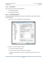
Page 40: ...Connecting Using PuTTY The following procedure describes how to connect to the S320 OCS using the PuTTY terminal emulation program 1 Open PuTTY The PuTTY Configuration window will appear 2 Specify you...

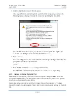
Page 41: ...switch with SSH and can begin entering commands at the prompt You should see output like this agent 5 Enter the TL1 command act user to log in to the switch The default TL1 username and password are...

Page 42: ...ble 3 Terminal Emulation Settings for the S320 OCS Item Value Data rate 115200 baud Bits 8 Parity None Stop bit 1 Set local echo Off Flow control None Terminal setting VT100 or ASCII Echo Off Line wra...

Reviews: