S320 OCS Getting Started Guide
Doc. Part No. 460166-00
June 29, 2015
Rev. D10
12 of 42
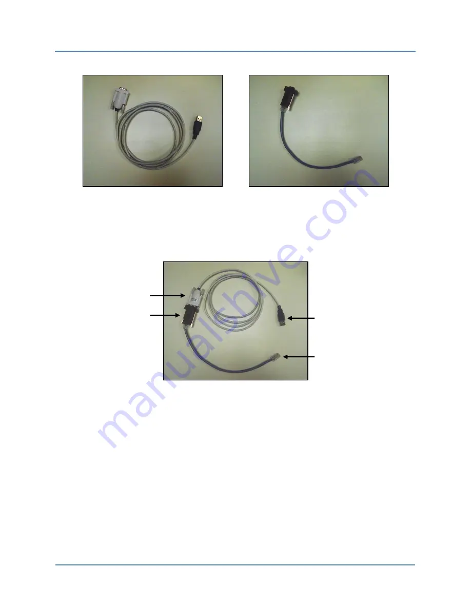
Figure 3 – USB-to-DB9 Cable (L) and RJ45-to-DB9 Adapter Cable (R)
2.
Connect the RJ45 end of the assembled serial cable (Figure 4) to the serial connector
located on the lower-right front of the S320 OCS (Figure 5 and Figure 8).
Figure 4 – Assembled Serial Cable
3.
Connect the USB end of the assembled cable to the serial connector on the host PC.
Once connected, the assembled serial cable appears as a COM port in the Windows Control
Panel Device Manager. If you are unsure which of the COM ports listed in the Device Manager
represents the serial cable, unplug the cable while viewing the Device Manager: whichever
COM port disappears is the serial cable port. The COM port will reappear in the Device Manager
when it is reconnected to the switch.
USB connector
RJ45 connector
DB9 adapter
DB9 connector


