background image


4


Operation: 

1.


Before 

lling the tank with material, thoroughly mix and strain the paint to remove skins or 

undissolved par

ti

cles with might otherwise block the 

ow of material through the hose and 

gun. A 

(

5

)

 gallon 

can 

of paint can be set inside the tank instead of pouring the paint into the 

tank. 

2.


Place lid assembly on tank and hand 

ti

ghten tank lid clamp screws. 

3.


Shut  o

  the  paint  tank  regulator  by  turning  T-handle  counter-clockwise.  Adjust  the 

compressor regulator to obtain the desired air pressure on the spray gun . 

4.


Now adjust the regulator on the paint tank to obtain the desired air pressure for the material. 
The higher above the paint tank you are spraying, the more pressure you will need on the 
material. Normal opera

ti

ng pressure on the paint tank is 

6

0 PSI. 

Should you wish to 

reduce  pressure,  simply  rotate  the  T-handle  adjus

ti

ng  screw  counter  clockwise  un

ti

l  the 

desired pressure se

tti

ng is obtained. There is no need to trigger the gun in order to bleed o


excess paint pressure. 


Warning: 


Do not use over 

8

0 PSI i

n your tank. 


Cleaning: 

Warning:

 Always shut o

 air pressure at source and bleed o

 all pressure in the paint 

tank by gently pulling safety valve before loosening thumb screw and clamps to remove 
lid. 


It is very important that the tank, material hose and spray gun be cleaned as soon as the 
spray job is 

nished. Turn o

 the main air supply to the tank. Remove all pressure from the 

tank by pulling on the safety valve un

ti

l the pressure bleeds down. Turn the T-handle 

adjus

ti

ng screw on the regulator counter-clockwise un

ti

l no spring tension is felt. 

Loosen thumb screws, 

ti

p clamps back and 

ti

p tank lid down to one side. Loosen spray gun 

air cap retaining ring about three turns then turn on the air supply. Cup cloth over air cap on 
the gun and pull trigger. This will force the material back through the hose. into the tank. 
Empty  and  clean  tank  and  parts  which  come  in  contact  with  the  material.  Use  a  suitable 
solvent. Pour solvent into the tank. Replace lid and 

ti

ghten the thumb screws and clamps and 

spray un

ti

l clean solvent appears. 


Summary of Contents for 365C

Page 1: ... risk factors The following hazards may occur when using this tool Damage to lungs if a dust mask is not worn Damage to hearing if hearing protection is not worn Wear eye protection California Air Tools 365C 5 Gallon Pressure Pot IMPORTANT Read all safety and operating instructions carefully before use Keep this Manual for reference ...

Page 2: ... make sure that equipment connected to tank or hose outlet has a higher pressure rating than the regulated air pressure in the tank Warning Risk of tank explosion 1 Modifications to the tank s design or construction could weaken it Assemble tank components in accordance with the service instructions Do not drill into tank or weld attachments or alter its design in any manner 2 Substitution of unaut...

Page 3: ...rise to dangerous levels If this reaction occurs within an enclosed structure such as this tank it may cause explosion Do not use reactive chemicals in your tank such as acids caustic solutions or halogenated hydrocarbon solvents 8 Over tightening clamps causing them to weaken and fail could result in the lid being propelled violently from the tank If the lid gasket leaks relieve the tank pressure...

Page 4: ...need to trigger the gun in order to bleed off excess paint pressure Warning Do not use over 80 PSI in your tank Cleaning Warning Always shut off air pressure at source and bleed off all pressure in the paint tank by gently pulling safety valve before loosening thumb screw and clamps to remove lid It is very important that the tank material hose and spray gun be cleaned as soon as the spray job is fini...

Page 5: ...y parts that are proven by an authorized service center to be defective in material or workmanship under normal use duringthe application warranty time period stated as above The limited warranty covers the cost of the replacement parts and labor for defects when installed by an authorized service center Transportation charges are the responsibility of the customer The limited warranty period begi...

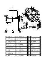
Page 6: ...7 18 19 20 21 22 23 24 25 26 27 28 29 30 31 32 33 34 35 36 37 38 39 Pressure gage Female male connector Valve Plug Tube Filter seat Filter washer Filter Filter circlip Sealing washer Cap Air converter Air Inlet plug Nut Fluid Inlet Plug Nut Gage connector voltage regulator Valve Air inlet seat Connector Air Outlet valve Safety valve assembly 3 8 Fluid Outlet Seat 3 8 Valve Fluid Outlet plug 1 3 3 ...

Page 7: ......

Reviews: