iL Series User Manual
California Instruments
Rev B
13
2.7.4 Remote Sense Connections
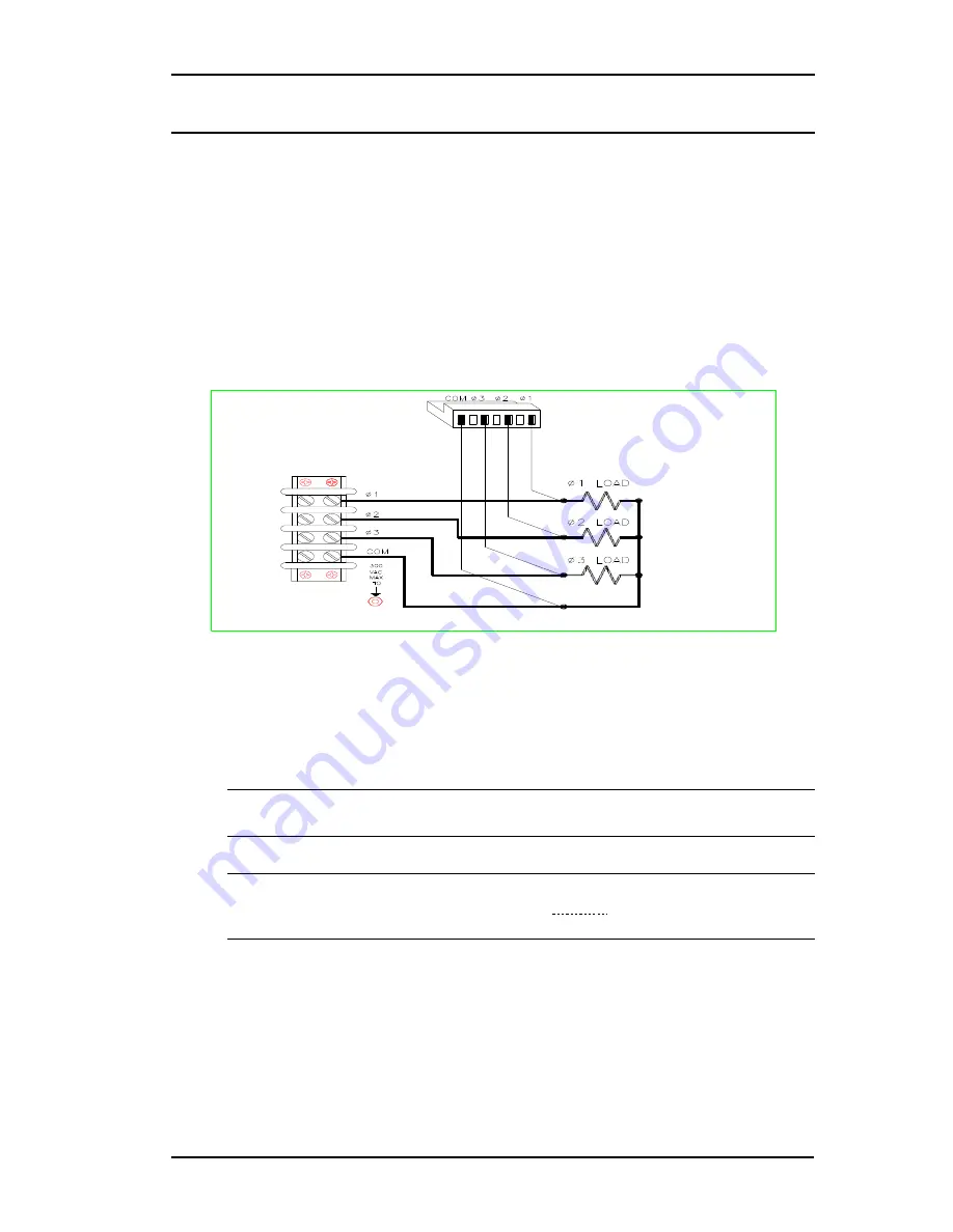
During operation, the AC source senses the output voltage at the output terminals on
the back of the unit. External sense terminals on the back of the unit allow the
output voltages to be sensed at the load, which compensates for impedance losses
in the load wiring. The sense connector accepts wires sizes from AWG 22 to AWG
12. Disconnect the mating plug to make your wire connections. As shown in the
following figure.
•
Connect the phase 1 (Ø1) through phase 3 (Ø3) sense terminals to the side of
the load that connects to the corresponding output terminal.
•
Connect the Neutral (COM) sense terminal connector to the neutral side of the
load.
Figure 7 Remote Sense Connections
The sense leads are part of the AC source's feedback path and must be kept at a
low resistance in order to maintain optimal performance. Connect the sense leads
carefully so that they do not become open-circuited. If the sense leads are left
unconnected or become open during operation, the AC source will regulate at the
output terminals, resulting in an increase in output over the programmed value.
Note: It is good engineering practice to twist and shield all signal wires to
and from the sense connectors.
Note: Set the ALC command to EXT (external) to enable remote sensing. The
ALC command is located under the
Voltage
key as explained in chapter
4. Set the ALC command to INT (internal) to disable remote sensing.
Summary of Contents for 3000iL
Page 9: ...iL Series User Manual California Instruments Rev B ix page intentionally left blank...
Page 10: ......
Page 37: ...iL Series User Manual California Instruments Rev B 27...
Page 89: ...iL Series User Manual California Instruments Rev B 79 Figure 23 AC Power Source Block Diagram...
Page 93: ...iL Series User Manual California Instruments Rev B 83 Figure 25 AC Input Board Parts Location...
Page 94: ...iL Series User Manual 84 Rev B California Instruments Figure 26 Mother Board Parts Location...


