iL Series User Manual
44
Rev B
California Instruments
Step
Action
Display
to change the duty cycle to 33 %.
6.
Access the Pulse menu and press
t
to access the pulse
period command. From the Entry keypad press .0 1 6 6
Enter to enter the period for 60 Hz (approximately 16.6
ms).
PER .0166
7.
Press Trigger Control and Enter to initiate the transient
trigger sequence.
INIT:IMMED
8.
Press Shift Trigger Control. This sends the AC source an
immediate trigger signal to generate the four output
pulses.
102 V 60 HZ
Table 33 : Programming a Voltage Pulse transient
Note: The AC source output returns to 102 V at the completion of the output
pulses.
In three-phase mode, the voltage pulses are phase selectable. You can output a
different voltage pulse for each phase. To do this, use Phase Select to first choose
the desired phase, as previously described in example 1 for setting the immediate
output voltage.
4.6.7 List Transient
Lists are the most flexible means of generating multiple or synchronized transient
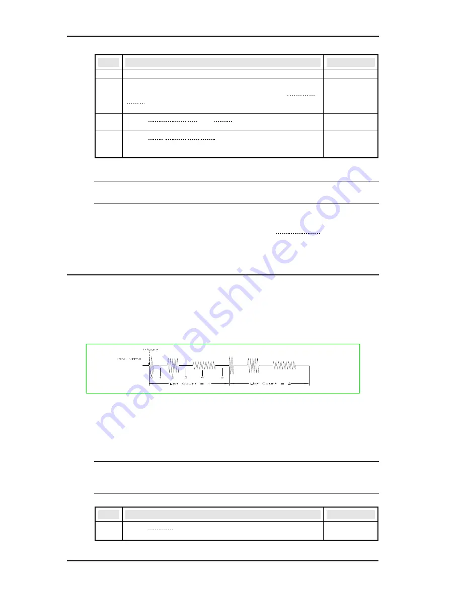
outputs. The following figure shows a voltage output generated from a list. The
output shown represents three different AC voltage pulses (160 volts for 33
milliseconds, 120 volts for 83 milliseconds, and 80 volts for 150 milliseconds)
separated by 67-millisecond, 0-volt intervals.
Figure 15 List Transients
The list specifies the pulses as three voltage points (point 0, 2, and 4), each with its
corresponding dwell point. The intervals are three zero-voltage points (point 1, 3,
and 5) of equal intervals. The count parameter causes the list to execute twice when
started by a single trigger.
Note: From the Output Menu execute the *RST command to reset the AC
source. This is necessary because any previously programmed
functions remain in effect until cleared.
Step
Action
Display
1.
Press Voltage to access the Voltage Menu. Then press
t
to access the voltage mode command.
VOLT:M
FIXED
Summary of Contents for 3000iL
Page 9: ...iL Series User Manual California Instruments Rev B ix page intentionally left blank...
Page 10: ......
Page 37: ...iL Series User Manual California Instruments Rev B 27...
Page 89: ...iL Series User Manual California Instruments Rev B 79 Figure 23 AC Power Source Block Diagram...
Page 93: ...iL Series User Manual California Instruments Rev B 83 Figure 25 AC Input Board Parts Location...
Page 94: ...iL Series User Manual 84 Rev B California Instruments Figure 26 Mother Board Parts Location...


