background image

California Trimmer Mower 

Maintenance Manual 


44 


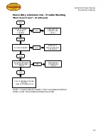
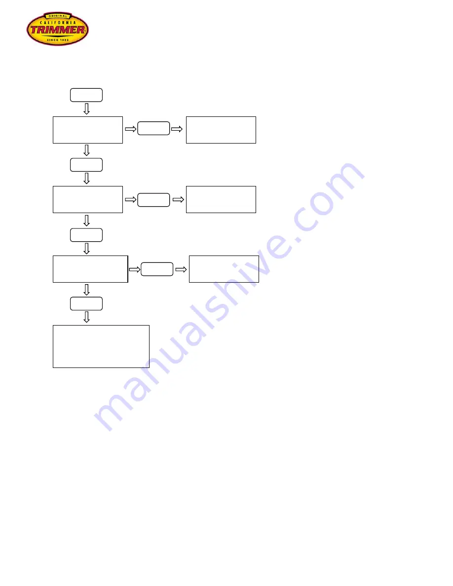
Heavy Duty & Commercial – Trouble Shooting 

“Reel doesn’t turn” – (Continued) 


NOTE 1: LOOK AT SHAFT INSIDE 17 TOOTH OUSIDE SPROCKET. 
NOTE 2: SHUT OFF ENGINE BEFORE ADJUSTING. 


IS THE 17 TOOTH 

SPROCKET 

TURNING? 

YES 

YES 

IS CHAIN TURNING?  

NO 

NO 

REPLACE SET 
SCREWS. SEE 

NOTE 2 

REPLACE 17 

TOOTH SPROCKET. 

SEE NOTE 2 

NO 

YES 

IS FRONT SPROCKET 

SPINNING ON REEL 

SHAFT? 

CALL CALIFORNIA TRIMMER 

OR VISIT 

WWW.CALTRIMMER.COM 

REPLACE SET 
SCREWS. SEE 

NOTE 2 

YES 

Summary of Contents for Mower

Page 1: ...CALIFORNIA TRIMMER MOWER MAINTENANCE MANUAL...

Page 2: ...California Trimmer Mower Maintenance Manual 2...

Page 3: ...els 12 Section 2 Home Owner Model Page Clutch Adjustment 14 Reel Adjustment 16 Roller Adjustment 18 Roller Assembly 20 Trouble Shooting Reel won t turn 22 Mower won t propel 23 Parts List and Mower Sc...

Page 4: ...hipping plastic and fully thread the coupling nut attached to the top section of the clutch rod onto the bottom section and tighten jam nuts Secure the clutch rod to the clutch lever on the handle wit...

Page 5: ...e of the handle Clutch Rod Assembly Remove the shipping plastic and fully thread the coupling nut attached to the top section of the clutch rod onto the bottom section and tighten jam nuts Secure the...

Page 6: ...California Trimmer Mower Maintenance Manual 6 Mower Maintenance Heavy Duty Commercial Models 6 4 1 2 4 6 6 3 5 6 3...

Page 7: ...y Loosen chain tensioner bolt adjust tensioner setting chain to desired tension and re tighten bolt Check roller chain tension once each week To tighter roller chain raise roller aligning the roller s...

Page 8: ..._______ ______________________________________________________________________________ ______________________________________________________________________________ __________________________________...

Page 9: ...r both top and bottom pieces Note 2 Remove carefully check for the reservoir gasket which may stick to the bottom section of the oil reservoir 3 The GX series engine has two oil plugs one in the front...

Page 10: ...tment lever no 2 towards the back of the mower will lower the height in small increments 1 3 2 4 5 6 To change the range setting take the height adjustment lever no 2 out of the holes of the quadrant...

Page 11: ...n On the Home Owner mower the short side goes to the right The catcher has three bale holes on each side to accommodate the bale at various height settings After setting mower to the desired height se...

Page 12: ..._______ ______________________________________________________________________________ ______________________________________________________________________________ __________________________________...

Page 13: ...H THE ENGINE TURNED OFF Step 1 With the clutch rod pointing down toward the engine in the engaged position see above the tip of the belt guard is just off the belt Adjust by bending the belt guard up...

Page 14: ...release bracket should be above parallel to the frame thus creating a slight bend in the belt Adjustments to the idler is made in the engaged position by loosening the set screw in the swivel and slid...

Page 15: ...The cutter bar adjusting screws raise and lower the cutter bar in relation to the reel Step 1 Disengage the clutch as shown below before adjusting the cutter bar Step 2 Turn one adjusting screw in sm...

Page 16: ...the above process with the opposite adjusting screw Step 4 Slide a piece of thin paper such as a page from a phone book or newspaper at small intervals all the way across the cutter bar to test for p...

Page 17: ...T BE MADE WITH THE ENGINE TURNED OFF Step 1 Loosen roller U Bolts and set screws on both sides of the drive roller This will loosen the drive roller on the yoke Step 2 Pull the drive roller back tensi...

Page 18: ...drive roller down past the furthest most position and the chain will become slack on the bottom Make sure the bolt heads on the sprocket clear the yoke when it spins Tighten the U Bolt and set screw o...

Page 19: ...s and the other end plate has six 6 holes Step 1 Starting with the end that has three 3 holes bolt the bearing holder and bearing using the bolts lock washers and washers Do not tighten Repeat on the...

Page 20: ...ket spacers over the remaining three 3 holes Install a 30 Tooth sprocket using the bolts lock washers and washers Try to center the sprocket as much as possible Make sure the roller spins freely If pr...

Page 21: ...S NO ADJUST REEL SEE INSTRUCTIONS REMOVE CHAIN GUARDS START ENGINE ENGAGE CLUTCH IS ENGINE PULLEY TURNING YES NO REPLACE SET SCREWS AND OR KEY SEE NOTE 2 IS BELT TURNING YES IS BOTTOM PULLEY TURNING Y...

Page 22: ...NG IS THE CHAIN TURNING YES YES IS DRIVESHAFT TURNING SEE NOTE 1 YES IS 17 TOOTH SPROCKETS TURNING REPLACE SET SCREWS SEE NOTE 2 YES NO NO YES NO NO NO REPLACE 8 TOOTH SPROCKET SEE NOTE 2 REPLACE DRIV...

Page 23: ...D YES NO ADJUST REEL SEE INSTRUCTIONS REMOVE CHAIN GUARDS START ENGINE ENGAGE CLUTCH IS ENGINE PULLEY TURNING YES NO REPLACE SET SCREWS AND OR KEY SEE NOTE 2 IS BELT TURNING YES IS BOTTOM PULLEY TURNI...

Page 24: ...E BEFORE ADJUSTING IS THE CHAIN TURNING YES IS DRIVESHAFT TURNING SEE NOTE 1 YES IS 8 TOOTH SPROCKET TURNING REPLACE SET SCREWS SEE NOTE 2 YES NO YES NO NO NO NO REPLACE 8 TOOTH SPROCKET SEE NOTE 2 RE...

Page 25: ...ion The air filters on some engines have an oil bath air filter and must be removed prior to tipping the mover forward to adjust the clutch forks Step 1 Tip the mower forward up onto the front part of...

Page 26: ...against the inner nut secures the desired tension of the spring Adjusting the Clutch Spring Tension Step 1 Disengage the clutch This will allow the drive sprocket to move slightly to the right and to...

Page 27: ...inued The proper spacing for the clutch is about the thickness or a nickel or quarter Press the drive sprocket over toward the large fork The proper spacing can be gauged between the clutch lining and...

Page 28: ...plates of the frame with the reel shaft hole toward the front to the mower at the 10 o clock position on the left hand side and the 2 o clock position on the right hand side or the mower Step 1 Three...

Page 29: ...ng holder moving the reel blades down toward the cutter bar The blades passing over the cutter bar will make a whooshing or metal to metal scraping sound If the reel blades are too close to the cutter...

Page 30: ...l to come out of adjustment When the reel is set in the desired position begin tightening all nuts and bolts Do not completely tighten the nuts and bolts as this could cause the reel and cutter bar to...

Page 31: ...MUST BE MADE WITH THE ENGINE TURNED OFF Step 1 Loosen roller U Bolts and set screws on both sides of the drive roller This will loosen the drive roller on the yoke Step 2 Pull the drive roller back te...

Page 32: ...drive roller down past the furthest most position and the chain will become slack on the bottom Make sure the bolt heads on the sprocket clear the yoke when it spins Tighten the U Bolt and set screw o...

Page 33: ...ay cause them to break off Remove the wheel s and spacer s Using a Pulley Puller remove the bearing holder from the other side NOTE Do not pull the bearing holder by the ears This may cause them to br...

Page 34: ...shaft either by inserting the short end of the drive shaft into a hole in your work bench or secure in a vice Take care not to dent or mar the surface of the drive shaft Step 1 Make sure the drive sha...

Page 35: ...nside of the oilite bushing If you do add grease to the bushing make sure that excess does not get on the clutch lining If the 39 tooth sprocket does not spin freely check the drive shaft and the bush...

Page 36: ...Place the drive shaft in a vise making sure to place a rag or cloth between the jaws of the vice and the drive shaft in order to prevent marring or scratching the surface of the drive shaft Step 6 Us...

Page 37: ...n the spring compression tool and remove from drive shaft Lightly file the two 2 indentations on the drive shaft left by the set screws if needed Check the length of the spring to make sure the collar...

Page 38: ...he mower Leave the two 2 set screws on the set collar loose until after the wheels have been installed Install the steady rest as shown grease zerk facing down Step 9 Install the first wheel on this s...

Page 39: ...ainst the bearing holder and tighten the two 2 set screws Align the roller drive sprocket with the roller sprocket and tighten the two 2 set screws be sure that one of the set screws is tightening on...

Page 40: ...earing holder with the bearing on one side of the roller shaft One end plate on the roller is set deeper inside the roller than the other Step 2 Install roller shaft with the bearing holder on the pla...

Page 41: ...er spins freely If the roller does not spin freely one or both of the bearings may be locked up on the shoulder of the roller shaft Using a hammer tap one or both sides of the roller shaft until the r...

Page 42: ..._______ ______________________________________________________________________________ ______________________________________________________________________________ __________________________________...

Page 43: ...E INSTRUCTIONS REMOVE CHAIN GUARDS START ENGINE ENGAGE CLUTCH IS ENGINE SPROCKET TURNING YES NO REPLACE SET SCREWS SEE NOTE 2 IS CHAIN TURNING YES IS BOTTOM 39 TOOTH SPROCKET TURNING YES NO REPLACE EN...

Page 44: ...NSIDE 17 TOOTH OUSIDE SPROCKET NOTE 2 SHUT OFF ENGINE BEFORE ADJUSTING IS THE 17 TOOTH SPROCKET TURNING YES YES IS CHAIN TURNING NO NO REPLACE SET SCREWS SEE NOTE 2 REPLACE 17 TOOTH SPROCKET SEE NOTE...

Page 45: ...L SEE INSTRUCTIONS REMOVE CHAIN GUARDS START ENGINE ENGAGE CLUTCH IS ENGINE SPROCKET TURNING YES NO REPLACE SET SCREWS SEE NOTE 2 IS CHAIN TURNING YES IS BOTTOM 39 TOOTH SPROCKET TURNING YES NO REPLAC...

Page 46: ...NSIDE 17 TOOTH OUSIDE SPROCKET NOTE 2 SHUT OFF ENGINE BEFORE ADJUSTING IS THE 17 TOOTH SPROCKET TURNING YES IS CHAIN TURNING NO NO REPLACE SET SCREWS SEE NOTE 2 REPLACE 17 TOOTH SPROCKET SEE NOTE 2 NO...

Page 47: ..._______ ______________________________________________________________________________ ______________________________________________________________________________ __________________________________...

Reviews: