HOVER MOWER OPERATOR’S MANUAL
California Trimmer
• 1028 4
th
St. SW, Bldg. A
• Auburn, Washington 98001 • CalTrimmer.com
Page 2
Introduction
Read this information carefully to learn how to operate
and maintain your product properly and to avoid injury
and product damage. You are responsible for operating
the product properly and safely.
Important:
This engine is not equipped with a spark
arrester muffler. It is a violation of California Public
Resource Code Section 4442 to use or operate the
engine on any forest-covered, brush-covered, or grass-
covered land. Other states or federal areas may have
similar laws. This spark ignition system complies with
Canadian ICES-002.
The enclosed Engine Owner's Manual is supplied for
information regarding the US Environmental Protection
Agency (EPA) and the California Emission Control
Regulation of emission systems, maintenance, and
warranty. Replacements may be ordered through the
engine manufacturer.
You may contact California Trimmer directly for product
and accessory information, help finding a dealer, or to
register your product. Whenever you need service,
genuine California Trimmer parts, or additional
information, please contact an Authorized Service
Dealer or Customer Service and have the model and
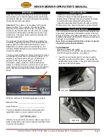
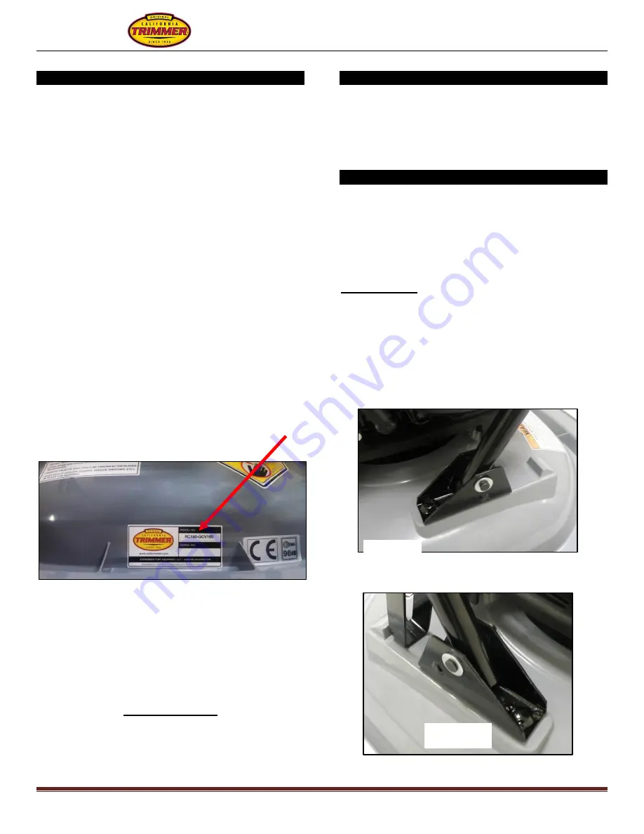
serial numbers of your product ready. They are located
on the decal on the rear of the unit as shown in this
photo:
Write the numbers in the following space provided.
Model Number: ____________________________
Serial Number: ____________________________
You may complete and mail the enclosed product
registration card or you can register on-line at:
CalTrimmer.com
Should you require warranty service, take a copy of your
sales receipt and a copy of your product registration card
to your servicing dealer.
Carton Contents
- California Trimmer Hover Mower
- California Trimmer Product Registration Card
-
Engine Owner’s Manual / Emission System Warranty
- Lower Handle Assembly (with handle stand)
- Upper Handle Assembly (including throttle control for
Honda engine only, engine stop lever and adjustment)
Assembly & Set-up
The unit has been carefully assembled with adjustments
and quality inspections performed by a team of trained
factory technicians who take great pride in their work. To
facilitate packaging and shipment, there are components
that need to be installed.
Note: It is recommended that this unit be set up and
checked by an Authorized Dealer.
Tools Required
- Regular or needle-nose pliers.
-
9/16” wrench and 1/2” wrench (for adjusting cutting
height and replacing blades
– see page 7)
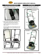
1. Insert the lower handle section into the mounting
brackets on each side of the deck
– noting that the
handle stand lever will be on the right side of the unit
as shown in the photo below.
Right Side
Left Side


