REEL MOWER OPERATOR
’S MANUAL (RL205H/207H)
Evergreen Turf Equipment
, LLC • 1028 4
th
St. SW, Bldg. A
• Auburn, Washington 98001 • caltrimmer.com
Introduction
Read this information carefully to learn how to operate and
maintain your product properly and to avoid injury and
product damage. You are responsible for operating the
product properly and safely.
You may contact Evergreen Turf Equipment directly for
product and accessory information, help finding a dealer,
or to register your product.
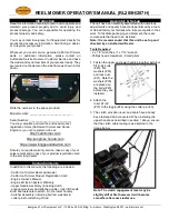
Whenever you need service, genuine California Trimmer
parts, or additional information, please contact an
Authorized Service Dealer or Customer Service and have
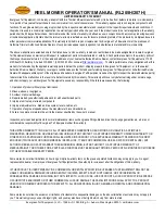
the model and serial numbers of your product ready. They
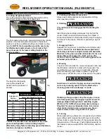
are located on the decal on the side frame as shown in this
photo…
Write the numbers in the space provided.
Model Number: ____________________________
Serial Number: ____________________________
You may complete and mail the enclosed product
registration forms (California Trimmer and Honda
Engine) or you can register on-line at:
http://caltrimmer.com
http://engines.honda.com
https://www.briggsandstratton.com
Should you require warranty service, take a copy of your
sales receipt and a copy of your product registration card
to the servicing dealer.
Carton Contents
In addition to this manual, the following are included…
- California Trimmer Reel Lawnmower
- California Trimmer Product Registration Card
-
Engine Owner’s Manual
- Engine Emission System Warranty
- Upper Handle Assembly (including clutch
engagement lever and attached cable), roller lift handle
& rod and fasteners to attach it to the lower handle)
- Catcher Assembly (including bail rod, washers &
cotter pins for attaching lift rod.
Assembly & Set-up
The unit has been carefully assembled with numerous
adjustments and quality inspections performed by a team
of trained factory technicians who take great pride in their
work. To facilitate packaging and shipment, there are
components that need to be installed.
Note: It is recommended that this unit be set up and
checked by an Authorized Dealer.
Tools Required
- 2 x 1/2
” wrenches / 1 x 7/16” wrench
- Phillips head screwdriver - Small pliers
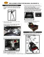
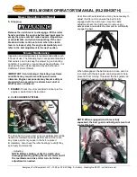
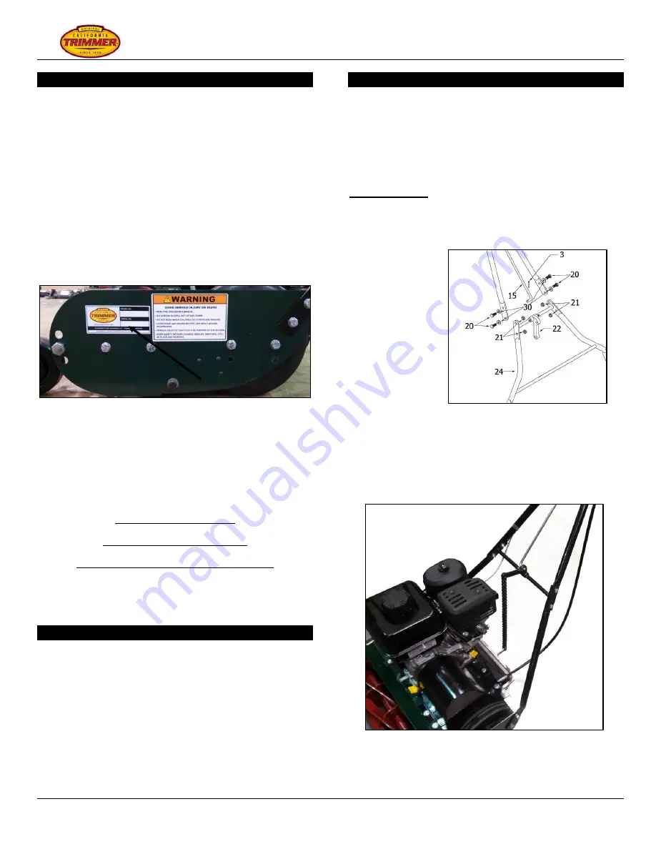
1. Fasten the upper and lower handles together with four
5/16
”-24 bolts
(#20), flat
washers (#30)
and lock nuts
(#21). Note the
washers (#30)
are placed on
the bolts (#20)
before they are
installed.
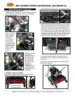
2. Attach the
roller lift rod
(#15) to the toggle (#22) using the cotter pin (#3).
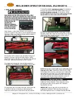
3. The clutch activation lever and cable have already
been fastened and connected. When installing the
upper handle as described in section 1 above, ensure
that the clutch cable routing is as depicted in the
image below.
Note: The clutch engagement lever may be
slightly stiff at first however it will become
smoother after some initial use.


