background image

System Maintenance

1. Remove the cell cap (the large black cap at the end of the clear cell housing) by turning it 

counter clock-wise.

2. Gently pull the cell electrodes out of the housing, being careful not to damage the O-Ring.

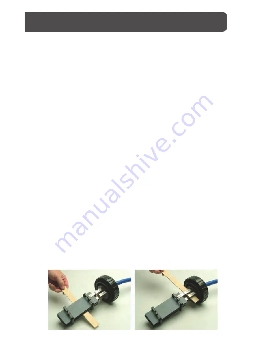
3. Once the cell is removed from the housing, slide the cleaning stick (the Platinum cleaning 

Device) between the blades to remove any calcium buildup (see Illustration on page 20). Make 

sure to clean the legs of the electrodes as well (see illustration on page 20). 

NOTE: THERE IS 

NO NEED TO USE ACID FOR THIS PROCESS AS IT REDUCES THE LIFE OF THE ELECTRODES.

4. Take the O-Ring out of the cell housing, and remove material or debris from it. Once you 

have cleaned the O-Ring, use a towel or Q-TIP to wipe out the channel in the cell housing that 

the O-Ring seats into.

5. Return the O-Ring to its channel in the cell housing 

(DO NOT USE LUBRICANT).

6. Install the electrodes into the cell housing, making sure not to disturb the O-Ring. Seat the 

tab on the top of the cell base into the indentation on the cell housing. If this is done correctly, 

the sensor located at the electrode base will be facing up in the 12:00 position.

7. Return the black cap to the cell housing and hand tighten in the clockwise direction. Be 

careful not to over tighten.

8. Re-start your pump; any loosened calcium will probably be brushed off with the water flow.

Cell Maintenance -- How and When to Clean Your Cell

Although the Platinum is a low maintenance reversing polarity system, occasional manual 

cleaning of the low maintenance Electrolytic cell will be required to remove scale and calcium 

build up. How often this cleaning is needed depends on the chemistry of the pool water, 

including the hardness of the water and how you balance your pool water chemistry, among 

other things. Although cleaning once every one to three months is fairly normal, periodic 

inspections of the Electrolytic cell through the clear housing (while the system is operating) is 

the best way to determine if the cell needs cleaning.

When to clean the cell is easily determined by a simple visual inspection of the cell while the 

Platinum system is operating. Carefully looking through the cell housing, check for buildup 

(which is easily seen) on the electrodes and the legs that attach the electrodes to the cell base 

(illustration on page 20). If there is no buildup, there is no need to clean the cell. If there is 

buildup, 

ALWAYS TURN OFF THE PUMP PRIOR TO CLEANING THE CELL. THE PUMP AND 

FILTER SYSTEM IS OPERATED UNDER PRESSURE, AND THE PRESSURE MUST BE RELIEVED 

BEFORE YOU WILL BE ABLE TO REMOVE THE CELL FROM THE CELL

HOUSING.

HOW TO CLEAN THE CELL

17

Summary of Contents for CMARSSG20-5

Page 1: ...CMARSSG20 5 CMARSSG40 5 CMARSSG60 5 20 000 Gallon System 40 000 Gallon System 60 000 Gallon System MODELS OWNER S MANUAL...

Page 2: ...critical to proper operation of the unit Problems or equipment failures resulting from the failure to maintain pool water chemistry in accordance with guidelines set forth in the Owner s Manual will v...

Page 3: ...lorinator Works 7 Water Preperations and Tips on Water Chemistry 7 Salt When and How to Add It 9 Salt Convertion Table 10 Chlorinator Installation 11 Installation Preperation 12 Installation Procedure...

Page 4: ...lectrician if you cannot verify the receptacle is protected by a GFCI 4 Do not bury cord Locate cord to minimize abuse from lawn mowers hedge trimmers and other equipment 5 WARNING To reduce the risk...

Page 5: ...ps To prevent cell damage and or personal injury do not in any way interfere with this system which has been designed for your protection CHEMICAL USE HAZARD To avoid personal injury when working with...

Page 6: ...ne generator is subject to the specifications of each body of water and should be carefully evaluated for best results Where heightened chlorine demand exists due to warmer climates humidity high bath...

Page 7: ......

Page 8: ......

Page 9: ......

Page 10: ...760 800 1800 147 182 220 258 293 330 367 403 440 477 513 550 587 523 660 697 733 2000 133 166 200 234 267 300 333 367 400 433 467 500 533 567 600 633 667 2200 120 150 180 210 240 270 300 330 360 390 4...

Page 11: ...rature LOCATED ON BOX The following tools will be required to install the Platinum system Screwdriver Level Hacksaw or PVC cutter Wire Stripping Tool Electric Drill 8AWG Copper Bonding Wire INSTALLING...

Page 12: ...urning on the pump All of the fittings are 2 inch PVC and if necessary can be reduced to 1 inch PVC The cell has a 10 foot power cord and cannot be modified use precaution to place the cell housing wi...

Page 13: ...hole slots on the wall bracket and allow the unit to hang freely Your Platinum Control Center is now mounted 5 Connect 8AWG bonding wire not included between the grounding rod and the grounding lug lo...

Page 14: ...d allow the cell to be removed for cleaning when neces sary 1 Balance your water chemistry according to the Water Chemistry Parameters shown on page 8 Add the proper amount of salt and circulate 24 ho...

Page 15: ...etween the cell blades The clear cell housing makes the monitoring of chlorine production and scale build up easy and visually accessible Control Center Functions 1 Sanitizer Output Lights shows level...

Page 16: ...used to offset out of the ordinary conditions unusual weather or extremely high bather load Unlike other chlorinators the Platinum is able to produce chlorine at all settings on the Sanitizer Output...

Page 17: ...ockwise direction Be careful not to over tighten 8 Re start your pump any loosened calcium will probably be brushed off with the water flow Cell Maintenance How and When to Clean Your Cell Although th...

Page 18: ......

Page 19: ...m Status light is ashing service light is yellow solid Increase Salt level by adding salt according to chart on Page 10 High Phosphates Metals High nitrate level Metals present in pool water Contact P...

Page 20: ...ave an experienced pool professional or an electrician con rm that the voltage is existent and correct Circuit breaker may be tripped Check the circuit breaker located on the control center box and re...

Page 21: ...21...

Page 22: ...Parts List 1 2 3 4 5 6 7 8 9 10 11 12 13 14 15 16 17 22...

Page 23: ...7 Grounding Lug 1 7 PC130 D1 10 Strain Relief 1 8 PC114 D2 10 Circuit Breaker 1 9 PC104 C3 2 Control Center Cover 1 10 PC123 D 2 1 Control Center Label 1 11 PC105 C3 5 On O Switch 1 12 CE107 C3 6 O Ri...

Page 24: ...tors com Register your warranty online sgschlorinators com warranty Visit us online www sgschlorinators com Manufactured by Saline Generating Systems LLC Record the Following Information Keep for Your...

Page 25: ......

Reviews: