8
Figure 9
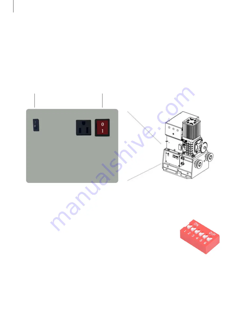
1. MUST use UL approved power wires, power wires MUST have a minimum capacity
for 15 Amp current.
2. All operators MUST be properly grounded in order to prevent an electrical charge.
Must use a dedicated circuit for power supply.
3. When the power is connected, turn the power switch to the ON position.
Installation
Step 4:
Connecting the Power
Power
Battery
See which direction your gate opens when viewed from the inside (exit side).
Figure 10
Step 5: Open Direction
Dip Switch #6 (Figure 10) on the bottom of the gate operator circuit board
controls the open direction.
ON
= opens to the right,
OFF
= opens to the left


