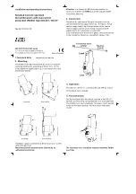
Installation instructions
1.
2.
3.
4.
5.
6.
7.
3
1
5
6
2
4
Front panel
Control light
please turn over!
Make a mounting breakthrough according the overleaf drawing
on a good approachable place as possible near the 230V shore
power inlet. The drawing is at scale 1 : 1, you can use it as pattern.
Remove the front panel. Remove the coat of the input- and output
cable (see scetch) and feed them through the holes at the bottom
of the housing. Remove the insulation of the wires and fix end
sleeves on the wire ends. Connect hereby the wires of the control
light with the wires of the input cable.
Connect the input cable with terminals 1 and 3, the output cable
with terminals 2 and 4 and both protective earthing conductors with
terminal 5.
Open the cable strain relief elements on the backside of the housing,
insert the input- and output cable and fix them.
Remove the insulation from the potential equalization wire (green/yellow
4mm²), fix an end sleeve on it and feed it through the hole at the bottom
of the housing. Open the strain relief element, insert the wire and fix it.
Connect the wire with terminal 6.
Put the Front panel on the housing and fasten the Panel 110 with the
enclosed screws. 230V at the input are indicated by the control light.
Carry out a function test of the ground-fault circuit interrupter according
the enclosed tutorial.
Connection diagram
Shore power unit with
ground-fault circuit interrupter


