21
Proprietary Information: Not for use or disclosure except by written agreement with Calix.
© Calix. All Rights Reserved.
3.
Create the service VLAN(s).
Create one VLAN per subscriber for the 1:1 provisioning model.
Create one VLAN per service for the N:1 provisioning model.
For video service, enable IGMP Snooping.
4.
Add the Ethernet uplink interface to the service VLAN memberships.
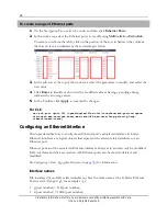
Configuring the Ethernet Uplink Port
The topic describes how to configure an E-Series Ethernet port for an uplink.
E-Series Ethernet ports and the associated Ethernet interfaces always exist and can only be
modified. LAG interfaces and their association with Ethernet ports can be created, deleted,
and modified. See
Configuring an Ethernet or LAG Interface
(on page
33
).
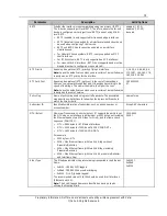
The physical characteristics of the underlying ports include:
Speed
Duplex setting
Interface type
ETH-Port names:
g(port number) = Gigabit Ethernet Ports (GE)
x(port number) = 10Gigabit Ethernet Ports (10GE)
Configuration guidelines
An Ethernet port is always a member of exactly one interface, even when it is being used
in a standalone manner.
An Ethernet port can be either assigned to the Ethernet interface associated with the
port, or assigned to an existing LAG interface. (Before you can assign a port to a LAG
interface, you must disable the port's default associated interface.)
The interface provisioning (for example, VLAN membership) applies to the port when
the interface is assigned to the port.
Keep the LACP role set to the default value of
active
, unless there is a very clear need.
Specifically, the topology where at least one side of the LAG is cross-card will not
operate when either side of the LAG is set to LACP role = passive.
When a port interface is added to an ERPS ring, the port attribute of Duplex defaults to
full
and the Flow Control setting defaults to
none
. If the port interface is removed from
the ERPS domain, these attributes can again be modified.
Destination lookup failure (DLF) based rate limiting should never be used on aggregation
network elements as this naturally happens when the access network goes through a
topology change. The use of this feature at the access node is also not advised as the rate
limiter indiscriminately applies to all services including business services.


