35
Proprietary Information: Not for use or disclosure except by written agreement with Calix.
© Calix. All Rights Reserved.
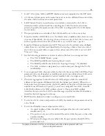
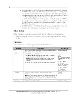
For modular chassis nodes, any VLAN created on the system is automatically mapped to the
Stacking Ports. The remaining port interfaces in the system must be a VLAN member for
traffic to pass on the VLAN through the interface.
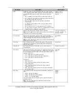
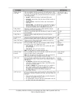
Interface role configuration guidelines
Trunk
Edge
Access
E7-2 or E-Series
X
X
X
E7-2 MCC
X
X
X
E7-2 MCE
X
E7-20 SCP
X
X
E7-20 GE-24
X
ONT Ethernet Port
X
Tag Actions
X
X
Native VLAN
X
X
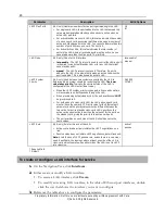
Networking Protocol
(RSTP, ERPS
*
, LAG)
X
X
*
Edge ports only support RSTP and LAG networking protocols, NOT ERPS.
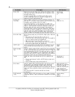
Link aggregation groups
The system uses IEEE 802.3ad/802.1AX Link Aggregation (LAG) to bond multiple GE or
10GE or 2.5GE ports (not mixed) into a single link aggregation group with a single logical
Ethernet interface. The ports that comprise a LAG can be on the same line card or on two
different line cards in the same shelf.
Link aggregation provides two principle values to the network operator:
Point to point link protection / redundancy between network elements
Bandwidth expansion of the logical interface beyond the capacity of a single link
You can configure the following LAG configurations:
The
active LAG
has all ports in the LAG active and the combined bandwidth of the
ports is available to carry the traffic on the logical link of the LAG. When a failure
occurs, the available bandwidth is reduced by the amount of bandwidth carried over the
failed port.
For a cross-card LAG, this configuration is known as
active/active
.
The
active/standby LAG
has multiple ports active and one or more port in standby,
positioned to come online when an active port fails.
For a cross-card LAG, a failure threshold defines how many active ports in the group can
fail before the group is taken out of service, and the system switches the LAG operation
to the ports on the standby card.

