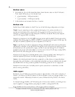
36
Proprietary Information: Not for use or disclosure except by written agreement with Calix.
© Calix. All Rights Reserved.
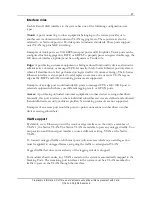
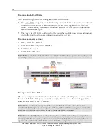
Example Single-Card LAGs
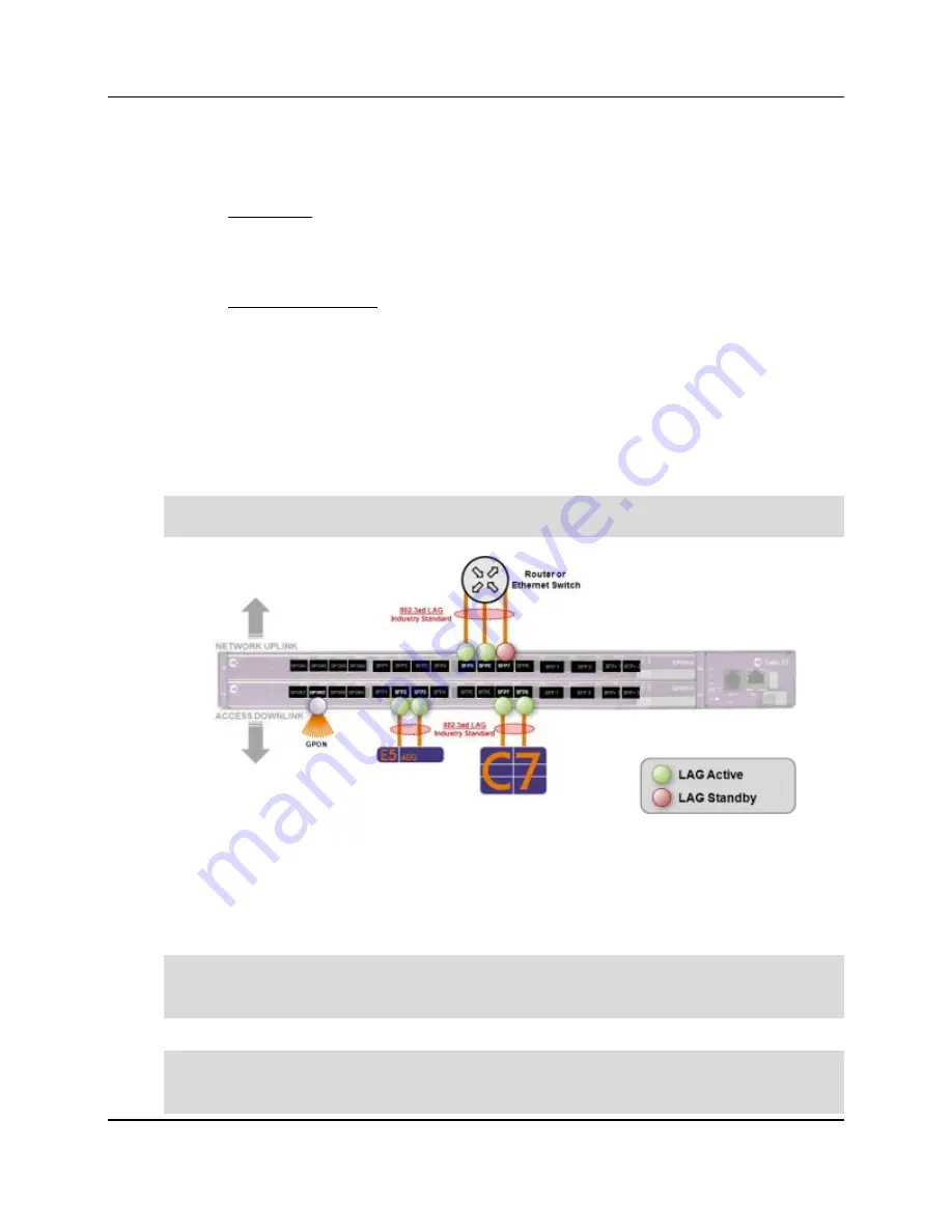
Two different single-card LAG configurations are shown below:
The active LAG configured for the E7 has all ports in the LAG active and the combined
bandwidth of the ports is available to carry the traffic on the logical link of the LAG.
When a failure occurs, the available bandwidth is reduced by the amount of bandwidth
carried over the failed port.
The active/standby LAG configured for the router has multiple ports active and one port
in standby, positioned to come online when an active port fails.
Example parameter settings:
RSTP Enabled = disabled
LAG cross-card = N (No) or disabled
LACP Min Ports = 1
LACP Max Ports = 2
**
Note:
**
Ports added to the LAG that exceed the LACP Max Ports parameter are designated
as standby ports.
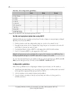
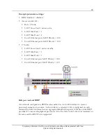
Example Cross-Card LAGs
The cross-card protection LAGs shown below have half of the LAG ports on one card and
the other half of the LAG ports on another card, in the same shelf. You can designate the
links on either card as active or standby.
Note:
If the number of active ports falls below the Min Ports value, then the system
switches the LAG operation to the ports on the standby card. When using cross-card LAG,
the LAG on the switch connected to the E7 must have RSTP disabled.
Note:
Keep the LACP role set to the default value of
active
, unless there is a very clear
need. Specifically, the topology where at least one side of the LAG is cross-card will not
operate when either side of the LAG is set to LACP role = passive.

