34
Proprietary Information: Not for use or disclosure except by written agreement with Calix.
© Calix. All Rights Reserved.
Connecting the E7-2 Management Interfaces
This section describes how to connect to the E7-2 management interface ports, including
front and rear Ethernet management ports and RS-232 serial port.
Connecting to the Ethernet Management Ports
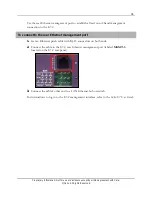
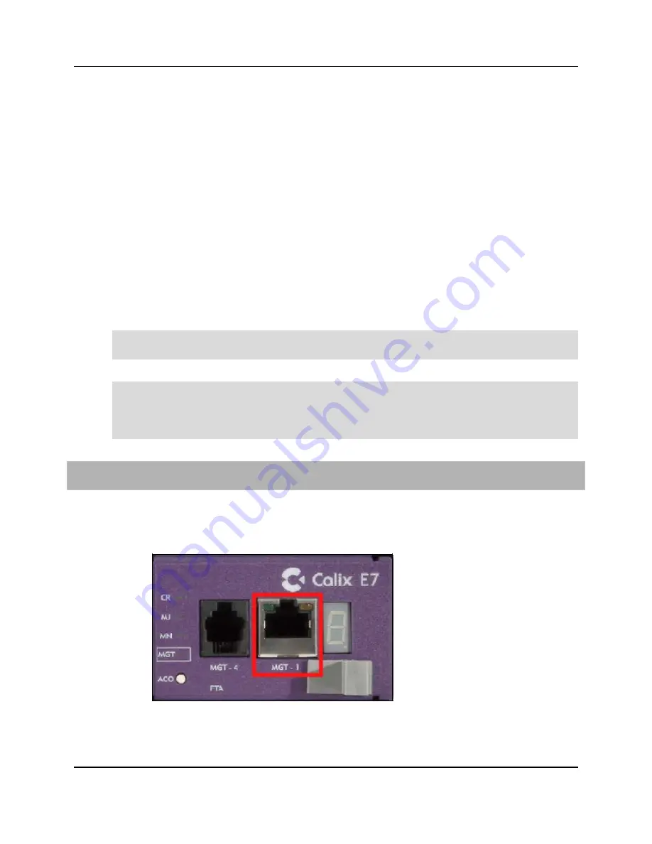
The Calix E7-2 is equipped with two out-of-band 10/100 Ethernet management ports (RJ-45
connectors). The front Ethernet management port is located on the E7-2 fan module
(labeled
MGT-1
). The rear Ethernet management port is located on the E7-2 rear panel
(labeled
MGMT-3
).
Use the front Ethernet port for (temporary) local Craft access to the E7-2. If you require a
permanent out-of-band management connection to the E7-2, Calix recommends using the
rear Ethernet management port to connect to the LAN.
Note:
Use a standard 'straight-through' Ethernet patch cable to connect to the E7-2
Ethernet management ports.
Note:
When you connect a disabled MGT port on the E7 to an Ethernet switch, the link
status lights on the switch light up (yellow, and then green after 30 seconds). A link is
established between the E7 and the switch, but the Management interface on the E7 is not
enabled and no traffic will pass over the link.
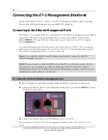
To connect to the front Ethernet management port
1.
Get a 'straight-through' Ethernet patch cable with RJ-45 connectors on both ends.
2.
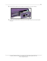
Connect the cable to the E7-2 front Ethernet management port (labeled
MGT-1
,
located
on the E7-2 fan module).
3.
Connect the cable's other end to the Ethernet port on your PC.
For instructions to log in to the E7-2 management interface, refer to the
Calix E7-2 User
Guide.
Summary of Contents for E7-2
Page 1: ...Calix E7 2 Installation Guide May 2013 220 00320 Rev 13...
Page 2: ......

