16
Appendix B - On and Off-Hook Detection (Voltage vs. Current)
The Whozz Calling? Deluxe detects when the phone is on-hook and off-hook. This allows the unit to determine the
length of each phone call and report this detailed information to the software. Telephone monitoring equipment can
detect the occurrence of the On Hook and Off Hook status of the phone line by two methods. It can either sense the
voltage on the phone line itself or sense current flow on a phone line passed through the equipment.
Voltages on incoming central office (CO) phone lines are consistent among all branches throughout a physical
location (building). If the voltage levels are in standard range, a Deluxe unit functioning in a voltage detection
mode is able to sense On and Off Hook on any branch in the building. The obvious advantage to this detection
scheme is that the monitoring equipment can be connected in parallel to the CO lines. Your unit comes from the
factory set to voltage detection mode because, in most locations, this detection scheme works properly.
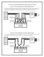
Current on phone lines only flows to the telephone device that is Off Hook. Monitoring equipment that senses On
and Off Hook by means of current flow must be connected between the phone company’s incoming line and the
device(s) that goes Off Hook. The current will flow through the monitoring equipment to the Off Hook device.
With this detection scheme, any telephone device that makes or receives phone calls must be attached in series (i.e
to the output jacks) “behind” the monitoring equipment.
VOLTAGE DETECTION CIRCUITRY AND TELEPHONE LINES
In order to sense the voltage on the phone line, the unit’s circuitry must draw a small amount of current from the
phone line. The current draw is very small (70
μ
A, similar to a voltmeter), and is drawn when the phone line is On
Hook. The telephone company’s amplifier supplying the power to your location may not be able to supply this
current and still keep the On Hook voltage level within the standard range. This occurs primarily in older
residential and commercial locations. An unsophisticated telephone company repair technician may diagnose this
small current draw by the unit as a “short” on the line. Therefore, the telephone company will not address the
shortcoming of their supply amplifier. If this situation occurs, the unit cannot be used in the voltage detection
mode, it must be reconfigured to the current detection mode.
RECONFIGURING UNIT TO CURRENT DETECTION MODE
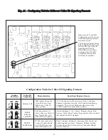
In order to configure the unit to a different Caller ID signaling format, the top of the enclosure must be removed and
shorting jumpers moved on the circuit board. Use the following steps and refer to Fig. B1 or Fig. B2 following.
1. Remove power to the unit.
2. Remove the top of the enclosure by first removing the two Phillips head screws on the bottom of the unit.
3. Slide the top of the enclosure off.
4. Locate the shorting jumpers on the circuit board (2 per channel and 1 main jumper) used for configuring
the unit to Current Detection using Fig. B1
5. Slide off the appropriate jumper(s) and reconnect as per lower diagrams based on the Version number of
the Printed Circuit Board (PCB).
-
Use Diagram B1 for PCB Version 6,7,or8.
- Use Diagram B2 for PCB Version 10 and above.
6. Replace the top of the enclosure and replace the two screws.


