background image

Page 18

Page 19

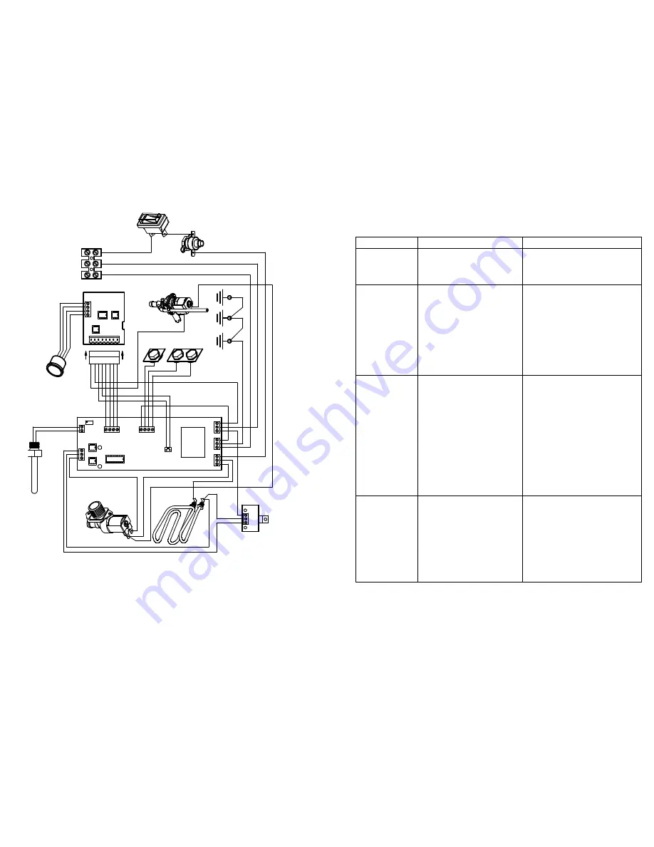
BASIC TROUBLE SHOOTING


Symptoms

Possible Cause

Remedy

No lights on 

front of unit

On / Off switch in Off position

Thermal cut-out tripped

Switch to On position

Reset and check for faults 

(i.e. scale on thermistor

No boiling water 
available

Normal  level sensor 
holding a signal

Thermal cut-out 
tripped (no lights on fascia)
On / Off switch in Off position

Element failed

De-scale

Reset and check for faults 
(i.e. scale on thermistor)
Switch to On position

Replace element

Thermal cut-out 
trips regularly

Excessive internal scale. (See 
‘De-Scale’ )

Faulty wiring to thermistors / 
faulty thermistors

Temperature controller needs 
adjusting 

Element failed to earth

Defective Main Printed Circuit 
Board & / or Triac PCB

De-scale the boiler 
(Particularly thermistor)

Repair / replace as required

Lower operating temperature

Replace element

Replace Circuit Board & Triac
(sold as a matched pair)

Overflows

Dirt in solenoid  valve.

Level sensors require de-
scaling or replacing

Main Printed Circuit 
Board faulty

Clean solenoid filter / or replace 
solenoid, “work the boiler” -
see Service Instructions 

De-scale / replace sensors

Replace Main Printed Circuit
Board 

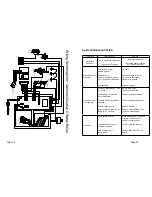
Wi
rin

g

 S

c

he
m

at

ic f
or

 Ca
lom
a

x Q

uas

ar

 2

 W
at

er

 B

o

ile

r

RE
D

YEL

L

O

W

BL
AC
K

BL
U

E

PI

N

K

BR
O

WN

OR

A

NG

E

WH

ITE

+1
2

Vd
c

 (

B

RO

W
N)

BL
AC
K

RE
D

0.

75
mm

 Y

E

LL
OW

0.

75
 W
H

IT

E

 O
R

 0

.5m
m

 Y

E

LL
OW

BL
AC
K

BL
AC
K

RE
D

N

E

L

BLUE

BLUE

L

N

E

BLACK

YELLOW / GREEN

BL
AC
K

BL
AC
K

YEL

L

OW

 / G
R

EE
N

RED

0V
d

c (
OR

A

NG

E

)

RE
D

RED

OR

A

NG

E

YEL

L

O

W

RE
D

BL
U

E

CONNECTOR PLUG

CO

L

D W

AT
E

R I
NL
E

T

SO
L

EN
O

ID
 V

AL
VE

EL
EM

EN
T

TR
IAC
 PC
B

HI
G

H

NO

RM

AL

LO
W

LE
V

EL

SEN

SO
RS

HO

T

 W
A

TE
R

 O
U

TL
E

T

DI
S

PE
N

SE V

AL
VE

HE
A

TE
R

LE
D

SO
L

EN
O

ID

LE
D

TH
E

RM

IST
O

R

PU
SH
 B

U

TTO

N

ON

 FR
O

NT

PAN

EL

TH
E

RM

A

L

CUT

O

UT

EAR

T

H

ON

 BO
D

Y

EAR

T

H

ON

 BA
S

E

OR

A

NG

E

BR
O

WN

OP
T

1

U1

OP
1

EAR

T

H O

N

CA
S

IN
G

SI

N

GL
E

 P

O

LE

IS

O

LA
T

IN
G

SW

ITC
H

Summary of Contents for QUASAR 2

Page 1: ...ND SERVICING INSTRUCTIONS Calomax Limited Lupton Avenue Leeds LS9 7DD Tel 0113 249 6681 Fax 0113 235 0358 e mail service calomax co uk www calomax co uk Please read these instructions carefully before...

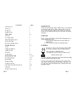
Page 2: ...TROUBLE SHOOTING 19 MAINTENANCE AND SERVICE HISTORY 20 22 WARRANTY 23 PRODUCT SPECIFICATION 24 CHECK LIST Before commencing installation check that the following parts have been supplied with the boi...

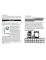
Page 3: ...ve must be fitted to the supply BEFORE CONNECTING THE SUPPLY PIPE MUST BE THOROUGHLY FLUSHED OUT TO ENSURE THAT FOREIGN MATTER DOES NOT BLOCK OR ENTER THE SOLENOID VALVE The boiler must be connected t...

Page 4: ...luminated On subsequent operation of the boiler The boiler will fill and heat in cycles It will allow only a limited amount of water to enter the unit at any one time and then switch off the solenoid...

Page 5: ...suitably qualified engineer GENERAL NOTES GENERAL OPERATION Avoid using any abrasive materials Wiping the outer casing with a damp cloth should be sufficient Some stainless steel cleaning products may...

Page 6: ...not rectify the problem turn off the water supply and remove the flexible hose to check for debris in the valve s filter The unit can be used normally while the service indicator is flashing a 4x puls...

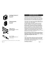
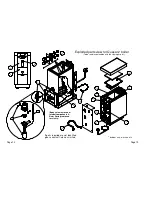
Page 7: ...equired are not identified please contact Calomax Limited Includes nuts washers etc Exploded parts view for Quasar 2 boiler To be read in conjunction with the spare parts list Body cut away to show in...

Page 8: ...tight joint Damage to the unit caused by a poor lid seal is not covered by warranty Scale deposits should be removed from all internal surfaces particularly the heating element thermistor and level s...

Page 9: ...DPBK NB15BLG CASSV CAP330 NBE3HK FIH CASMR CASLPK NBPRG MULLER DISPENSE VALVE GROMMET DISPENSE VALVE SERVICE KIT MAIN PRINTED CIRCUIT BOARD Inc TRIAC WATER DISPENSE PUSH BUTTON Inc FITTING TOOL AUXIL...

Page 10: ...place as required Lower operating temperature Replace element Replace Circuit Board Triac sold as a matched pair Overflows Dirt in solenoid valve Level sensors require de scaling or replacing Main Pri...

Page 11: ...Page 20 Page 21 MAINTENANCE AND SERVICE HISTORY MAINTENANCE AND SERVICE HISTORY...

Page 12: ...s are beyond our control and would invalidate the warranty offered These include Incorrect installation High Low water pressure Incorrect voltage supply Accidental damage Limescale build up The last i...

Page 13: ...ate from dispense valve 2 8 Litres Minute Voltage 220 240 V ac 50 60 Hz Power rating 3kW MAX PLEASE ENTER SERIAL NUMBER FOR FUTURE REFERENCE Note All measurements are approximate PLEASECONTACTOURSERVI...

Reviews: