background image

 58

1002595 ISSUE 5 M172 VARIHEAT

VARIHEAT AA SYSTEM OWNER INSTALLATION MANUAL

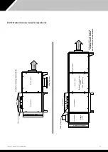
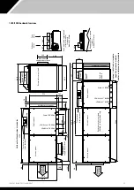
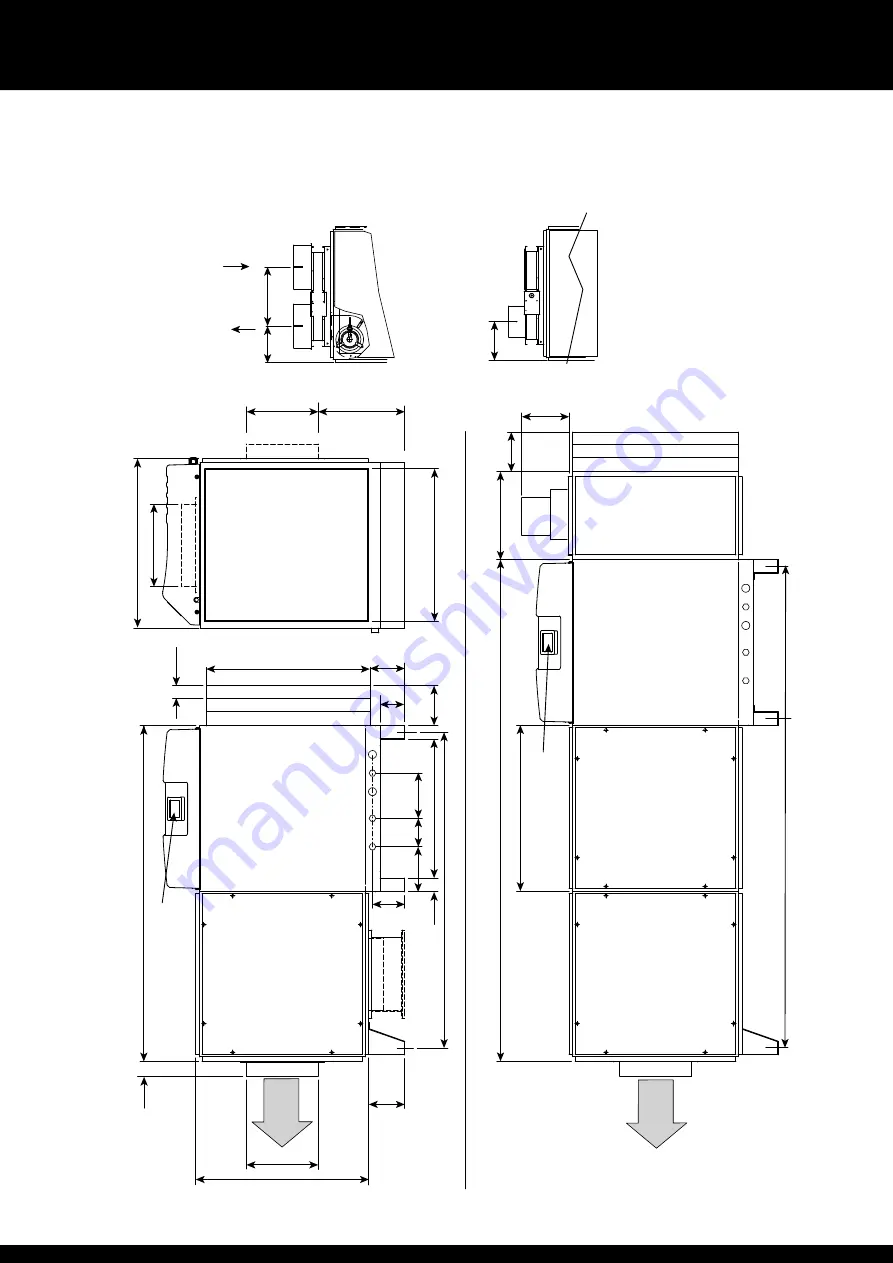
600/900 horizontal versions

Negativ

e pr

essur

e module

1 spigot

diameter 157mm

Fr

esh air module spigot detail

(V

ie

w f

rom air on)

2 spigots

diameter 225mm

302

187

Spigot

Spigot

Damper

203

Fr

esh

air in

Exhaust air out

Fr

esh air

module

Service panel

670

2024

355

160

Air filter access panel

Variheat with f

resh air module,

negativ

e pr

essur

e module

and/or r

esistance heater module

Resistance heater module (if r

eqd) in this position only

Service panel

190

Service panel

Spigots 

See

right

Supply air to

pool hall

LPHW in ¾" BSPM

LPHW out ¾" BSPM

Drain ¾" BSPM

Electric box assembly

Service panel

Touchscr

een

User Interface

1943

Variheat without optional modules

289

60

698

Service panel

1274


Service panel

182

115

183

130

160

560

56

662

Air filter access panel

50

148

1354

100

140

Return air f

rom pool hall

333

Supply air to

pool hall

615

683.5

289

Alternative 

supply air positions

349

Alternativ

e

supply air position

LPHW in ¾" BSPM

LPHW out ¾" BSPM

Drain ¾" BSPM

Electric box assembly

Touchscr

een

User Interface

Supply air to

pool hall

Summary of Contents for Variheat AA1200

Page 1: ...1 1002595 ISSUE 5 M172 VARIHEAT Variheat system AA600 900 1200 1500 Owner installation manual 1002595 issue 5...

Page 2: ......

Page 3: ...INE LOCATION 34 3 2 FRESH AIR AND EXHAUST AIR 36 3 3 PLUMBING INSTALLATION 37 3 4 ELECTRICAL CONNECTIONS 39 3 5 ELECTRICAL INSTALLATION 40 3 6 VOLT FREE TERMINALS AND REMOTE ACCESS 42 3 7 NETWORK CONN...

Page 4: ...or instruction concerning the use of the appliance in a safe way and understand the hazards involved Children should not play with the appliance Cleaning and maintenance shall not be made by children...

Page 5: ...heat pump dehumidifier that is automatically controlled to remove unwanted humidity from the swimming pool hall The heat recovery will contribute signi cantly towards the hall heating requirements Th...

Page 6: ...re any servicing or electrical work commences When unlit power is disconnected but remote interfaces connected to the Variheat from other systems may still be live Ethernet port for connection to a lo...

Page 7: ...a white background can be modified except where locked by the User Security settings Grey buttons and parameters with a grey background cannot be modified See page 20 Pressing the button shows the sec...

Page 8: ...C Number shows current measurement Outer ring shows current measurement blue bar in relation to current Occupied mode setting red arrow Press the centre to change temperature setting Key to lights Ye...

Page 9: ...tandby Variheat is powered but not operating The Variheat has been put into Standby via the user touchscreen See caution below To enable the Variheat press the red touchscreen button Orange and black...

Page 10: ...me clock to control the Occupied and Unoccupied periods of the Variheat The left hand button sets the Variheat into Occupied mode The right hand button sets the Variheat into Unoccupied mode If remote...

Page 11: ...rol of the environment If you y Increase the water temperature evaporation from the swimming pool water will increase running costs will increase and the likelihood of condensation will increase y Red...

Page 12: ...or Unoccupied Mode according to y User time period settings y User override button y Remote system connected to the interface terminals In Occupied Mode all functions operate according to User Settin...

Page 13: ...d is shown at the top The allowable range that the parameter can be changed between is shown underneath 1 4 DATA ENTRY SECURITY MODE If Security Mode is enabled see page 20 some functions may not be a...

Page 14: ...ing the cog button on the second Home screen Controller Clock Occupied Unoccupied periods Alarms Set Points and Switches Language User Security Data Monitoring USER SETTINGS INSERT THE PIN AND PRESS T...

Page 15: ...s isolated from power or if there is an interruption to the power supply which lasts longer than three days DAYLIGHT SAVING TIME This button is red when daylight saving is disabled and green when dayl...

Page 16: ...period is required period B can be disabled AA LPHW models only The current Occupied air temperature and the Unoccupied air temperature settings are shown The Unoccupied setting is set as the differe...

Page 17: ...ings menu The Alarms screen displays warnings or faults with the Variheat indicated by a red highlight The example above indicates that there is a problem with the air filter that should be investigat...

Page 18: ...n Return to Home screen This screen duplicates settings on the Home screens If functions on the Home screens are disabled by the User Security settings they may be accessed here Note the buttons on th...

Page 19: ...GE Press this button on the Settings menu Arrow icon Return to User Settings Home icon Return to Home screen The available languages are shown on this screen and can be selected by pressing the button...

Page 20: ...Arrow icon Return to User Settings Home icon Return to Home screen Password Disabled Password Disabled When Security Mode is enabled the buttons shown on the screen can be toggled between grey and ora...

Page 21: ...y default Webgate password is DefaultPass For security reasons the Dantherm Group recommend that this password is changed If the password is changed write it in the box below and keep this manual in a...

Page 22: ...me screen Pressing the buttons brings up a graph of the selected parameter Choose from Air temperature Humidity Water temperature and Alarms The display is marked up in hours and shows the past 72 hou...

Page 23: ...creen Settings Customer Timers IP Address BMS Settings Reset to Factory settings Advanced Settings Press this button on the Settings menu WARNING ACCESSING THE ADVANCED SETTINGS BY PUTTING IN THE ONE...

Page 24: ...here to improve accuracy For example the Variheat displays an air temperature of 29 5 C and a calibrated thermometer measures 30 0 C In this instance an offset of 0 5 C can be applied to calibrate the...

Page 25: ...ome screen The Reset Standby Switch on Power Loss button determines what happens when power is interrupted When set to ON the Variheat restarts in Standby mode when power is reconnected and does not f...

Page 26: ...CUSTOMER TIMERS Press this button on the Advanced Settings menu Arrow icon Return to User Settings Home icon Return to Home screen Defrost Pulse Time Defrost Timeout should be left as defaults setting...

Page 27: ...s button on the Advanced Settings menu Arrow icon Return to User Settings Home icon Return to Home screen This screen contains settings related to remote access by an Android iOS device or ActiveX bro...

Page 28: ...5 115200 Protocol Used Can be set from 2 to 4 corresponding to 2 uNET 3 Modbus RTU 4 BACnet MS TP Data Bit Always set to 8 Included for information only to configure own software if needed Parity Bit...

Page 29: ...see the BMS Settings screen on page 31 Enable DHCP This button toggles between DHCP enabled or disabled IP Address Subnet Mask Default Gateway Primary and Secondary DNS all fields can be set from 0 t...

Page 30: ...ired see section 2 1 Network setting If the Variheat is only to be accessed by devices connected to the same network no further network setup is necessary If the Variheat is to be accessed from device...

Page 31: ...twork the Variheat is connected to using another device that is connected to the same network Search for What is my IP in a search engine and make a note Ensure port forwarding has been set on the rou...

Page 32: ...Variheat Controller appears y Click Monitoring in menu bar of the main window y Click In Frame or New Window from under Webgate in the left hand menu y When the login window appears login with the us...

Page 33: ...will be supplied complete but if necessary the fan module and fresh air module where fitted may be separated to assist positioning where plantroom access is restricted The following actions need to be...

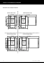
Page 34: ...o pool hall Supply air to pool hall Service panel Service panel Return air from pool hall Return air from pool hall Alternative supply air positions Water connections Service panel if not ducted Alter...

Page 35: ...ptional resistance heater module in this position only Touchscreen user interface Return air from pool hall Return air from pool hall Optional resistance heater module in this position only Service pa...

Page 36: ...is less than 7m then a full height separator panel may be required to prevent recirculation Exhaust air out Fresh air in Return air from pool hall Notes 1 Ensure duct work pressure drop including all...

Page 37: ...cts the water removed by the dehumidification process It is therefore necessary to ensure that the Variheat III is placed on a level plinth so that the condensate can run away and not overflow the edg...

Page 38: ...issioning set Flow setting pressure gauges method Customers tun dish Copper stub Drain to waste U trap VH3 drain Variheat III unit DRAIN BSPM AIR FILTER ACCESS PANEL AIR FILTER ACCESS PANEL Variheat w...

Page 39: ...ative position if this is more convenient for the user to access With the power isolated and the black cover removed the screen rear can be removed by pressing the button on top The screen can be unsc...

Page 40: ...ther in performance or warranty terms Voltage Minimum Maximum Single phase machines 207V 253V Three phase machines 360V 440V Frequency 47 5Hz 52 5Hz Note The voltage must be measured at the heat pump...

Page 41: ...4 2 2 1 E L1 MCB 3 5 4 6 L2L3 Customer terminations to heater module See notes in section 3 7 Separate mains supply terminal blocks for resistance heater modules layout single and three phase no conn...

Page 42: ...REMOTE ACCESS Fire alarm 230V AC Link if not used 10 11 12 13 14 15 16 17 18 19 20 1 2 Occupied Unoccupied Volt free Remote On Off Link if not used Main Fan Fault Link if not used Common Fuse 800mA M...

Page 43: ...be used Time clock override remote Occupied Unoccupied control terminals 10 11 For remote control of the Variheat Occupied Unoccupied mode To enable Occupied mode the remote switch should be closed T...

Page 44: ...witches screen in the User Settings but only while Frost Protection is active 3 7 NETWORK CONNECTION Local area network connection For screen mirroring to function see Section 2 2 Remote access the Va...

Page 45: ...BACnet MS TP Modbus is available via the RS485 2 interface on the PLC BACnet IP is available via the Ethernet port on the PLC BACnet MS TP is available via the RS485 2 interface on the PLC Only one B...

Page 46: ...easurement of the conditions When using 0 5mm cable the maximum total distance between the sensors and their terminals is 20 metres After the Remote Sensor Box has been connected it may be necessary t...

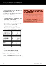
Page 47: ...e Pool hall and plant room 9 Check is the building finished in accordance with the original plans and specification ready for commissioning Check current temperatures and humidity calibrate air water...

Page 48: ...See 4 1 4 1 MAINTENANCE Operations carried out during a planned maintenance visit are as follows 1 Replace all belts filters where fitted 2 Check operation and condition of all fans and compressors 3...

Page 49: ...25 24 23 COMPRESSOR SANYO PANASONIC COMPRESSOR ONLY C S R 27 28 10V Vsp GND RES HEATER CONTROL IF FITTED FAN MOTOR L N 5 7 6 TO FIRE ALARM RELAY R2 9 6 45 46 0 10V INPUT 10V Vsp GND FRESH AIR BOX FAN...

Page 50: ...CN19 CN2 HMI SCREEN 24V DC FG COM 1 DAMPER POSITION MAIN FAN SPEED EXHAUST FAN SPEED MAIN FAN FAULT REMOTE ON OFF OCC UNOCCUPIED R1 FIRE ALARM RELAY FORCE VENTILATION MAIN FAN FILTER BLOCKED GND A01 A...

Page 51: ...PROBE DEFROST TEMPERATURE PROBE COM D1 DI9 DI10 DI11 DI12 CN12 CN13 AI9 AI10 AI11 AI12 GND 5V DC 24V DC RMINALS LOAD 500mA FUSE 16 800mA DEFROST VALVE 230V FAN RELAY COMPRESSOR CONTACTOR R2 R3 C34 CN...

Page 52: ...RE ALARM RELAY FORCE VENTILATION MAIN FAN FILTER BLOCKED GND A01 A02 A03 A04 CN3 COM D1 DI1 DI2 CN4 COM D1 DI3 DI4 DI5 DI6 DI7 DI8 POWER SUPPLY MEMORY CARD MICRO SD MAINS LAMP RCU RELAY RCU MCB IF FIT...

Page 53: ...E PROBE RESISTANCE HEATER FAN STAT COM D1 DI9 DI10 DI11 DI12 CN12 CN13 AI9 AI10 AI11 AI12 GND 5V DC 24V DC MINALS OAD 500mA FUSE 16 800mA FUSE 6 800mA BOILER GO FUSE 63 160mA REMOTE DAMPER DEFROST VAL...

Page 54: ...ign air flow anemometer air on filter wet evaporator 10 Maximum external static pressure standard LPHW Maximum external static pressure upgraded LPHW Design running amps 230V 1N fans Design running am...

Page 55: ...w rate L min 22 22 22 22 22 return temperature C 61 8 55 4 49 1 42 7 39 5 C 65 60 55 50 45 AA600 upgraded air heating capacity kW 12 8 11 0 9 2 7 3 5 5 recommended boiler capacity kW 12 8 11 0 9 2 7 3...

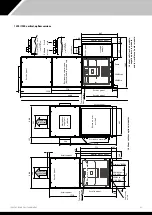
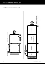
Page 56: ...sistance heater module If fitted In this position only 670 Spigots See above 190 60 160 1180 Air filter access panel Service panel Variheat with fresh module negative pressure module and or resistance...

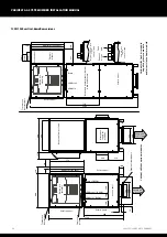
Page 57: ...ressure module and or resistance heater module Resistance heater module if fitted In this position only Service panel 2199 355 Spigots See below 160 190 Service panel Fresh air module 2 spigots diamet...

Page 58: ...module Resistance heater module if reqd in this position only Service panel 190 Service panel Spigots See right Supply air to pool hall LPHW in BSPM LPHW out BSPM Drain BSPM Electric box assembly Serv...

Page 59: ...s position only Service panel Electric box assembly Service panel Supply air to pool hall Service panel Service panel Service panel Variheat without optional modules Service panel Service panel Air fi...

Page 60: ...1 729 800 Cabinet 71 222 355 784 1558 Cabinet 33 33 Floor duct adaptor supplied Floor duct adaptor supplied 149 Cabinet foot Cabinet foot Cabinet foot Floor duct adaptor supplied Cabinet foot Cabinet...

Page 61: ...optional modules 190 160 60 1558 945 182 140 260 1295 Air filter access panel Service panel Service panel Variheat with fresh air module negative pressure module and or resistance heater module Supply...

Page 62: ...r module Resistance heater module if filled in this position only Service panel 2503 289 Service panel Service panel 772 Air filter access panel 50 642 56 100 160 1734 355 920 180 140 260 800 Service...

Page 63: ...rseeure module and or resistance heater module Resistance heater module if fitted in this position only Service panel 190 Spigot Alternative 2249 Service panel Supply air to pool hall 289 Fresh air mo...

Page 64: ...r module Service panel Air filter access panel Service panel Variheat with fresh air module negative pressure module and or resistance heater module Resistance heater module if fitted in this position...

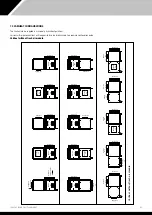
Page 65: ...Return air Supply air to pool hall Supply air Supply air Supply air Supply air Supply air Supply air Supply air Supply air Supply air Electric box Electric box Electric box Electric box Electric box E...

Page 66: ...eturn air Supply air Supply air Supply air Supply air Supply air Electric box Electric box Electric box Electric box Electric box Electric box Electric box Electric box Electric box Electric box Suppl...

Page 67: ...Return air Return air Return air Return air Return air Return air Return air Return air Return air Return air Supply air to pool hall Supply air Supply air Supply air Supply air Supply air Supply air...

Page 68: ...rrect 9 The fan amps and duct pressure are outside the specified limits 10 The air flow to and from the machine is outside the specified limits 11 Corrosion is present due to poor air quality that has...

Page 69: ...69 1002595 ISSUE 5 M172 VARIHEAT...

Page 70: ...70 1002595 ISSUE 5 M172 VARIHEAT...

Page 71: ...71 1002595 ISSUE 5 M172 VARIHEAT...

Page 72: ...Dantherm Ltd Unit 12 Galliford Road Maldon CM9 4XD United Kingdom 44 0 1621 856611 sales uk dantherm com Calorex is part of the danthermgroup co uk...

Reviews: