CALREC
Putting Sound in the Picture
113
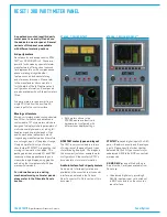
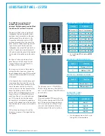
DIPswitchconfiguration
PCB mounted DIP switches provide
some configuration options for moving
coil meters. To access these switches,
the panel needs to be removed from the
control surface. Once removed, the drive
card for the meters is accessible from the
rear.
Level
A bank of 4 switches is used on each
audio leg to set the level to be displayed
on the meters at line-up. These are
adjusted to compensate for the meter
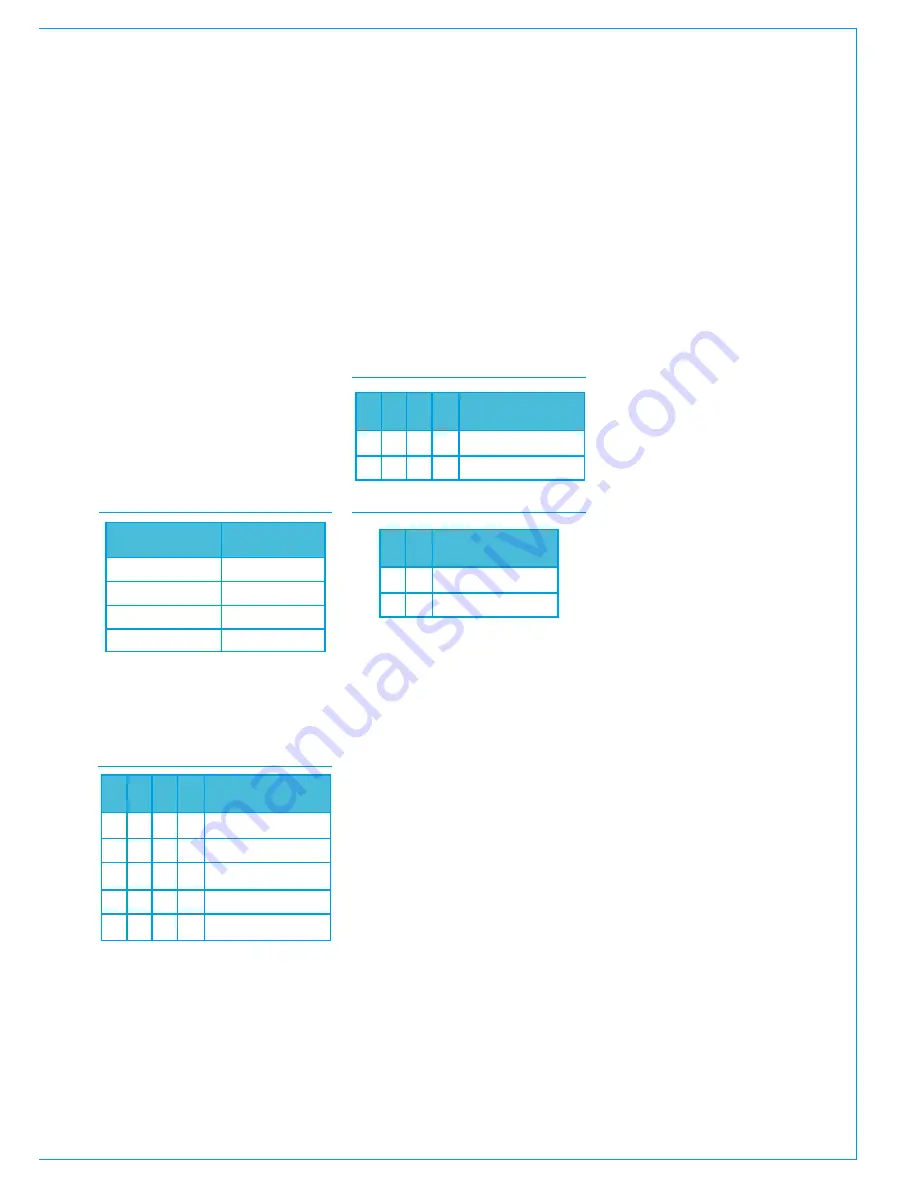
type and operating level. The table below
shows which bank of switches is used for
each audio channel.
CHANNEL LEVEL SWITCHES
Audio Path
VU 1 / PPM 1L
VU 2 / PPM 1R
PPM 2L
PPM 2R
Switch
SW 4
SW 1
SW 3
SW 2
Each bank of four switches should be set
as per the table below for the required
line-up level:
LEVEL SWITCH SETTINGS
1
2
3
4
Level
0
0
0
0
1
0
0
0
1
0
0
1
1
0
1
0
1
1
0
0
0
-2
-4
-6
-9
L/RorM/S
If fitted with dual needle PPM meters, the
right hand unit can be set to display left
/ right stereo, or M/S (sum / difference).
DIP switch 5 should be set accordingly
as shown in the following table. In M/S
mode, the mono sum can be a standard
A+B-6, or it can be set to A+B-3, using
DIP switch 6.
SWITCH 5 - L/R / M/S
SWITCH 6 - A+B-6/-3
Resets
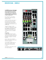
Three reset buttons along with an enable
button are located in the centre of this
panel. As a safety precaution, to activate
a reset, the enable button must also be
pressed as well as the desired reset
button. The resets are split into three
areas -
• 'DSP' resets the audio signal
processing cards in the processing
core.
• 'Control' resets the Master Control
processors in the processing core.
• 'Surface' resets the control surface
panels.
Talkbackmic
A female XLR is provided to connect
the supplied goose-neck microphone.
This connects directly to an XLR on the
rear interface panel (no gain or power is
applied in the console). The microphone
can be connected into an external
talkback system, or the console's own
talkback system via a Hydra2 input.
Please refer to the console configuration
section for details on console talkback
setup.
USBport
The USB port on this panel connects
directly to a USB port on the console
PC, providing convenient access for file
transfer, such as memory backups.
The spare USB-Ethernet adaptor can also
be connected to this USB port to provide
a temporary second network connection
to the PC if the rear interface panel is not
as convenient to access.
1
2
3
4
Operation
1
0
1
0
1
0
1
0
L/R
M/S
1
2
Operation
0
0
1
1
A+B-6
A+B-3
Summary of Contents for Artemis
Page 5: ...calrec com Putting Sound in the Picture ARTEMIS INFORMATION...
Page 9: ...calrec com Putting Sound in the Picture ARTEMIS CONTROL SURFACE...
Page 26: ...26 ARTEMIS Digital Broadcast Production Console...
Page 27: ...calrec com Putting Sound in the Picture ARTEMIS PROCESSING CORE BEAM SHINE...
Page 33: ...calrec com Putting Sound in the Picture ARTEMIS PROCESSING CORE LIGHT...
Page 40: ...40 ARTEMIS Digital Broadcast Production Console...
Page 41: ...calrec com Putting Sound in the Picture ARTEMIS CONNECTION INFORMATION...
Page 66: ...66 ARTEMIS Digital Broadcast Production Console...
Page 67: ...calrec com Putting Sound in the Picture ARTEMIS EXTERNAL CONTROL...
Page 80: ...80 ARTEMIS Digital Broadcast Production Console...
Page 81: ...calrec com Putting Sound in the Picture ARTEMIS SETUP CONFIGURATION...
Page 100: ...100 ARTEMIS Digital Broadcast Production Console...
Page 101: ...calrec com Putting Sound in the Picture ARTEMIS PANEL OPTIONS...
Page 110: ...110 ARTEMIS Digital Broadcast Production Console...
Page 111: ...calrec com Putting Sound in the Picture ARTEMIS OBSOLETE PANELS...
Page 114: ...114 ARTEMIS Digital Broadcast Production Console...
Page 115: ...calrec com Putting Sound in the Picture ARTEMIS SPECIFICATIONS...

