


20 ARTEMIS
Digital Broadcast Production Console
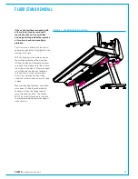
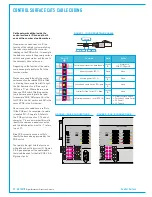
Control Surface
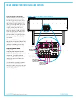
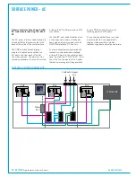
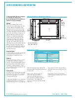
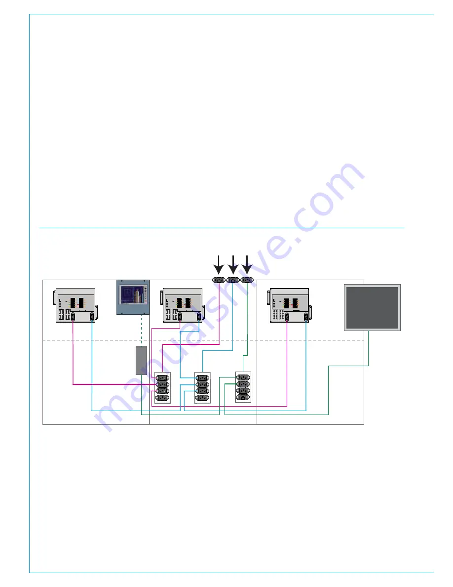
Artemis control surfaces have 3 x IEC
AC mains inputs requiring 100–240V
AC.
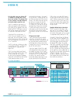
The AC power inlets are wired internally to
three distribution blocks mounted to the
base of the inside of the control surface.
The POE switches have dual power
supplies for redundancy and take two
AC inputs, one from each of the first
two mains sources. The majority of the
remaining hardware in the control surface,
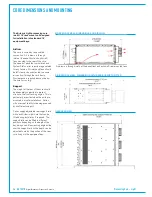
SURFACE AC POWER CONNECTIONS
P1
P2
P3
P4
P5
P6
S1
S2
USB
YZ5706 - POE SWITCH
P
S
AP
SPR
RST
AP1
AP2
AP3
AP4
SPR1
SPR2
RST
RST
A
B
2
1
POWER
GOOD
A
B
AC IN 1
AC IN 2
P1
P2
P3
P4
P5
P6
S1
S2
Panel
Surface switch
Ancillary Power
Surface switch
Power & Reset
Reset
-
-
-
-
-
Serial number
P1
P2
P3
P4
P5
P6
S1
S2
USB
YZ5706 - POE SWITCH
P
S
AP
SPR
RST
AP1
AP2
AP3
AP4
SPR1
SPR2
RST
RST
A
B
2
1
POWER
GOOD
A
B
AC IN 1
AC IN 2
P1
P2
P3
P4
P5
P6
S1
S2
Panel
Surface switch
Ancillary Power
Surface switch
Power & Reset
Reset
-
-
-
-
-
Serial number
P1
P2
P3
P4
P5
P6
S1
S2
USB
YZ5706 - POE SWITCH
P
S
AP
SPR
RST
AP1
AP2
AP3
AP4
SPR1
SPR2
RST
RST
A
B
2
1
POWER
GOOD
A
B
AC IN 1
AC IN 2
P1
P2
P3
P4
P5
P6
S1
S2
Panel
Surface switch
Ancillary Power
Surface switch
Power & Reset
Reset
-
-
-
-
-
Serial number
MU5734
1
md
04/03/08
Approved
Calrec
Alpha
RTW meter 10600
Meter Module
..
..
Meter
PSU
POE
POE
POE
PC MONITOR
Surface AC inputs
1
2 Anc
SURFACE POWER - AC
including the PC is DC powered via POE
connections.
The third IEC input and distribution block
is used to power ancillary or third party
items with a single mains input, such as
DK/RTW meters and PC monitors.
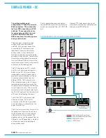
To ensure all equipment is powered and
redundancy is applied where available,
all three IEC inputs to the control surface
need to be fed with 100–240V AC. If only
one of the first two inputs is fed, System
Status error messages will be generated
by each POE indicating they are not
receiving power on both inputs.
It is recommended that these two mains
inputs are fed from two separate AC
supplies where possible to provide
redundancy against external power failure.
Summary of Contents for Artemis
Page 5: ...calrec com Putting Sound in the Picture ARTEMIS INFORMATION...
Page 9: ...calrec com Putting Sound in the Picture ARTEMIS CONTROL SURFACE...
Page 26: ...26 ARTEMIS Digital Broadcast Production Console...
Page 27: ...calrec com Putting Sound in the Picture ARTEMIS PROCESSING CORE BEAM SHINE...
Page 33: ...calrec com Putting Sound in the Picture ARTEMIS PROCESSING CORE LIGHT...
Page 40: ...40 ARTEMIS Digital Broadcast Production Console...
Page 41: ...calrec com Putting Sound in the Picture ARTEMIS CONNECTION INFORMATION...
Page 66: ...66 ARTEMIS Digital Broadcast Production Console...
Page 67: ...calrec com Putting Sound in the Picture ARTEMIS EXTERNAL CONTROL...
Page 80: ...80 ARTEMIS Digital Broadcast Production Console...
Page 81: ...calrec com Putting Sound in the Picture ARTEMIS SETUP CONFIGURATION...
Page 100: ...100 ARTEMIS Digital Broadcast Production Console...
Page 101: ...calrec com Putting Sound in the Picture ARTEMIS PANEL OPTIONS...
Page 110: ...110 ARTEMIS Digital Broadcast Production Console...
Page 111: ...calrec com Putting Sound in the Picture ARTEMIS OBSOLETE PANELS...
Page 114: ...114 ARTEMIS Digital Broadcast Production Console...
Page 115: ...calrec com Putting Sound in the Picture ARTEMIS SPECIFICATIONS...


