


CALREC
Putting Sound in the Picture
21
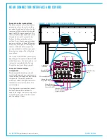
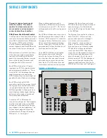
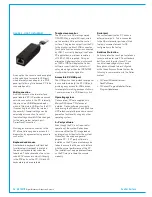
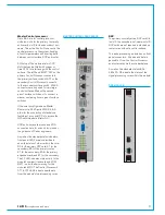
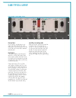
The surface switches and
configuration PC take DC power via
RJ45 connectors. These should be
fed from SPR connections on POE
switches. These connections are
for power only—no data is carried
over the POE SPR connections.
SPR connections do not drop power
during surface reset.
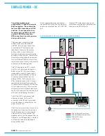
The power input connectors on the
surface switches are labelled PR1
and PR2. Only one input needs to be
connected for full functionality and
redundancy. If power to the primary
surface switch is lost, or the switch
fails, data is automatically routed via the
secondary Surface Switch. Therefore the
two surface switches should be powered
from two different POE units to maintain
overall console functionality in the event of
a failure of a POE feeding power.
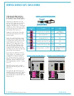
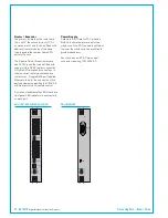
The PC is powered via a DC convertor
unit. This unit has two power inputs on
RJ45s for the PC. Only one of these
is required for operation, the second is
provided for power redundancy. These
connections should be fed from two
different POE's. SPR connections on
POE's should be used so the PC power
is maintained during surface reset. The
PC power convertor outputs 12V DC via a
9 way D-type connector. This wires via a
momentary switch in the keyboard tray to
the PC's DC input jack. The switch acts as
a PC reset by interrupting the power.
The PC has 2 DC input jack sockets,
either can be used. Only one DC
connection to the PC itself is provided
as the redundancy is catered for by the
power convertor unit.
The PC power convertor box also contains
the headphone driver circuitry and has a
3rd RJ45 power input for this, situated
in the bottom row of connectors. The
headphone driver can be powered from an
SPR port or an AP depending on whether
or not power needs to be maintained
during surface reset.
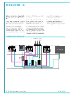
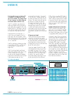
SURFACE POWER - DC
Control panels take power and data on
the same RJ45 connection and therefore
need to be connected from a P1–P6 POE
port.
P1
P2
P3
P4
P5
P6
S1
S2
USB
YZ5706 - POE SWITCH
P
S
AP
SPR
RST
AP1
AP2
AP3
AP4
SPR1
SPR2
RST
RST
A
B
2
1
POWER
GOOD
A
B
AC IN 1
AC IN 2
P1
P2
P3
P4
P5
P6
S1
S2
Panel
Surface switch
Ancillary Power
Surface switch
Power & Reset
Reset
-
-
-
-
-
Serial number
P1
P2
P3
P4
P5
P6
S1
S2
USB
YZ5706 - POE SWITCH
P
S
AP
SPR
RST
AP1
AP2
AP3
AP4
SPR1
SPR2
RST
RST
A
B
2
1
POWER
GOOD
A
B
AC IN 1
AC IN 2
P1
P2
P3
P4
P5
P6
S1
S2
Panel
Surface switch
Ancillary Power
Surface switch
Power & Reset
Reset
-
-
-
-
-
Serial number
P1
P2
P3
P4
P5
P6
S1
S2
USB
YZ5706 - POE SWITCH
P
S
AP
SPR
RST
AP1
AP2
AP3
AP4
SPR1
SPR2
RST
RST
A
B
2
1
POWER
GOOD
A
B
AC IN 1
AC IN 2
P1
P2
P3
P4
P5
P6
S1
S2
Panel
Surface switch
Ancillary Power
Surface switch
Power & Reset
Reset
-
-
-
-
-
Serial number
USB
YZ5716-2
Surface Switch
IP
PS
PR
PS1
PS2
PS3
PS4
PS5
PS6
PR1
PR2
- Input Power
- POE Switch
- Power & Reset
IP2
2
4
6
1
3
5
IP1
A
B
Serial number
USB
YZ5716-2
Surface Switch
IP
PS
PR
PS1
PS2
PS3
PS4
PS5
PS6
PR1
PR2
- Input Power
- POE Switch
- Power & Reset
IP2
2
4
6
1
3
5
IP1
A
B
Serial number
Serial number
PC5787
POE SW 1
SPR1/2
POE SW 2
SPR1/2
PC POWER (+12V)
+ PC RESET
POE SW
SPARE PWR
BALANCED
ANALOG INPUTS
HEADPHONE
OUTPUTS
PC & Headphone Driver
Power Convertor
PC
PC Reset Switch
POE Cat5 Surface Switch Power
POE Cat5 Headphone Driver Power
POE Cat5 PC Power
12V PC Power
Upstand TFT meter panels, moving coil
meters and miscellaneous optional panels
take power via POE AP ports.
SURFACE SWITCH, PC AND HEADPHONE DRIVER POWER
Summary of Contents for Artemis
Page 5: ...calrec com Putting Sound in the Picture ARTEMIS INFORMATION...
Page 9: ...calrec com Putting Sound in the Picture ARTEMIS CONTROL SURFACE...
Page 26: ...26 ARTEMIS Digital Broadcast Production Console...
Page 27: ...calrec com Putting Sound in the Picture ARTEMIS PROCESSING CORE BEAM SHINE...
Page 33: ...calrec com Putting Sound in the Picture ARTEMIS PROCESSING CORE LIGHT...
Page 40: ...40 ARTEMIS Digital Broadcast Production Console...
Page 41: ...calrec com Putting Sound in the Picture ARTEMIS CONNECTION INFORMATION...
Page 66: ...66 ARTEMIS Digital Broadcast Production Console...
Page 67: ...calrec com Putting Sound in the Picture ARTEMIS EXTERNAL CONTROL...
Page 80: ...80 ARTEMIS Digital Broadcast Production Console...
Page 81: ...calrec com Putting Sound in the Picture ARTEMIS SETUP CONFIGURATION...
Page 100: ...100 ARTEMIS Digital Broadcast Production Console...
Page 101: ...calrec com Putting Sound in the Picture ARTEMIS PANEL OPTIONS...
Page 110: ...110 ARTEMIS Digital Broadcast Production Console...
Page 111: ...calrec com Putting Sound in the Picture ARTEMIS OBSOLETE PANELS...
Page 114: ...114 ARTEMIS Digital Broadcast Production Console...
Page 115: ...calrec com Putting Sound in the Picture ARTEMIS SPECIFICATIONS...


