


CALREC
Putting Sound in the Picture
31
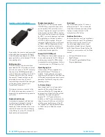
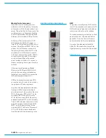
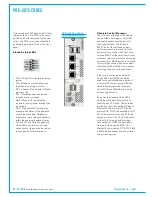
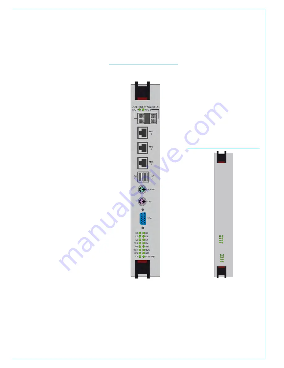
MasterControlprocessor
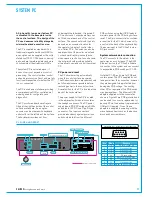
Slots 4 & 5 are for control processor
modules, slot 4 for the primary / normally
active card, slot 5 for the secondary / hot-
spare. The active Control Processor is the
central processor in the system, handling
all control parameters and directing data
between control surface, DSP and router.
At the top of the module are two SFP
slots that can be fitted with copper or
fibre SFP's for interfacing with the control
surface. The left hand 'MAC7' SFP on the
primary Control Processor connects to
the primary surface switch, MAC7 on the
secondary Control Processor connects
to the secondary surface switch. MAC6
connectors are only used for very large
control surfaces fitted with a second
pair of surface switches, or to connect a
sidecar containing its own pair of surface
switches.
If the core is configured as a Master
Router core, RJ45 ports MAC 3, 4 & 5
allow for the connection of standalone
(outside of a console) PC's to access the
H20 network administrator GUI.
USB ports, keyboard, mouse and VGA
connections are for use only by, or under
the guidance of Calrec engineers.
As well as the standard status indicators,
front panel LED's are also provided to
show the status of other cards in the core:
D0 for the primary DSP card; D1 for the
secondary; R0 for the primary router;
R1 for the secondary; E0 for the primary
expansion card; and E1 for the secondary.
The CF LED indicates write activity to the
module's compact flash card and LOW
BATT is a low battery warning for the
module's BIOS. The Control Processor's
ST1 & ST2 LED's indicate heartbeats
from the module's two processing cores.
MASTER CONTROL PROCESSOR
DSP
The primary, normally active DSP card fits
in slot 3, the secondary, hot-spare in slot 6.
DSP cards are not required in standalone
router cores without a control surface.
This audio processing module has no front
panel connectors. All audio and data is
passed to / from the Control Processor
and router cards via the core backplane.
As well as the standard status LEDs,
LEDs D1–D8 indicate the status of the
signal processing cores within the module.
DSP
POK
MA
PRI
RST
MOK
NOK
ST1
ST2
D1
D2
D3
D4
D5
D6
D7
D8
DSP MODULE
Summary of Contents for Artemis
Page 5: ...calrec com Putting Sound in the Picture ARTEMIS INFORMATION...
Page 9: ...calrec com Putting Sound in the Picture ARTEMIS CONTROL SURFACE...
Page 26: ...26 ARTEMIS Digital Broadcast Production Console...
Page 27: ...calrec com Putting Sound in the Picture ARTEMIS PROCESSING CORE BEAM SHINE...
Page 33: ...calrec com Putting Sound in the Picture ARTEMIS PROCESSING CORE LIGHT...
Page 40: ...40 ARTEMIS Digital Broadcast Production Console...
Page 41: ...calrec com Putting Sound in the Picture ARTEMIS CONNECTION INFORMATION...
Page 66: ...66 ARTEMIS Digital Broadcast Production Console...
Page 67: ...calrec com Putting Sound in the Picture ARTEMIS EXTERNAL CONTROL...
Page 80: ...80 ARTEMIS Digital Broadcast Production Console...
Page 81: ...calrec com Putting Sound in the Picture ARTEMIS SETUP CONFIGURATION...
Page 100: ...100 ARTEMIS Digital Broadcast Production Console...
Page 101: ...calrec com Putting Sound in the Picture ARTEMIS PANEL OPTIONS...
Page 110: ...110 ARTEMIS Digital Broadcast Production Console...
Page 111: ...calrec com Putting Sound in the Picture ARTEMIS OBSOLETE PANELS...
Page 114: ...114 ARTEMIS Digital Broadcast Production Console...
Page 115: ...calrec com Putting Sound in the Picture ARTEMIS SPECIFICATIONS...


