


CALREC
Putting Sound in the Picture
77
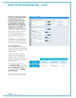
Perle units supplied by Calrec can
be pre-configured if the connectivity
requirements are communicated prior
to delivery. Please discuss 3rd party
control integration with your Calrec
sales representative or assigned
project leader.
Configuration requires that the IP
addresses of the Perle unit itself are
known. If the addresses are not known, or
have yet to be configured, the first stage
requires a serial Telnet connection to the
front panel console port, labelled Admin.
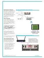
TelnetIPconfiguration
The front panel Admin console port, like
the rear panel serial ports is RS232 on an
RJ45 connector.
Perle supply the units with a number of
various cable adaptors. Use the female
D9 to RJ45 socket adaptor, along with an
Ethernet cable, to connect a PC serial port
to the Perle front panel Admin console
port (the RJ45 plug to RJ45 socket cable
adaptor, labelled 'Console Port' is not
required).
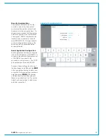
Launch a Telnet application on the
PC. The following instructions are
based around using HyperTerminal,
which is normally pre-installed on
Windows PC's. HyperTerminal
can be found under
Windows
Start>All Programs>Accessories>
Communications
.
On starting a new HyperTerminal session,
you are required to enter a name of
your choice and select an icon. On the
following page, select
COM1
(or the PC
port being used if different) from the
Connect Using
drop-down menu.
Enter the port settings on the following
page as follows;
bits per second: 9600,
data bits: 8, parity: none, stop bits: 1,
flow control: none.
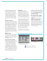
PERLE IOLAN CONFIGURATION
Once the connection is configured, the
main HyperTerminal window should be
in view. Ensure the connection is active
by clicking the
Call
icon (telephone
with handset down) at the top of the
HyperTerminal window. If the icon is
greyed out, it is already connected.
Once HyperTerminal is connected, power
up the Perle unit. On boot up, messaging
from the Perle unit should be displayed in
the HyperTerminal window. Once booted,
you should be greeted with a login prompt.
To login, enter
admin,
for the password,
enter
superuser
. A successful login
is greeted with the unit's model number
(SCS8#).
Enter the following to set the IP address
for the Perle Ethernet port 1:
set
server internet eth1 xxx.xxx.
xxx.xxx
(substituting xxx.xxx.xxx.xxx
with the desired IP address). Enter the
following to set port 2:
set server
internet eth2 xxx.xxx.xxx.xxx
Enter
save
then
y
to confirm and
retain the changes.
Note, the IP addresses chosen for
the Perle unit need to be in a range
compatible with those of the Calrec cards
being connected to (or their alternate,
aliased IP addresses).
Cycle the power to the Perle unit to
reboot and view the startup messaging to
confirm the IP addresses have been set
correctly. Note, in the boot up messaging,
port 1 is displayed as 'eth0' and port 2
'eth1' - this is contrary to the commands
required to set the IP's.
Call (connect) icon
Disconnect icon
Mainconfiguration-WebManager
Once the IP addresses of the Perle unit
are known, the main configuration can be
carried out.
Connect an Ethernet cable from a PC
Ethernet port to one of the two Ethernet
ports on the rear of the Perle unit.
Configure the network connection of the
PC to be in a compatible IP address range
with the Perle unit. Launch a web browser
on the PC and enter the IP address of the
Perle's port 1 into the browsers address
field to bring up the Perle Web Manager
application.
Enter
admin
for the username and
superuser
for the password to log in.
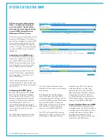
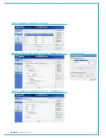
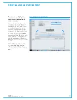
Select the
Configuration>Network>IP
Address / IP Settings
page, either from
the tree on the left, or by the selection
buttons in the main screen (screenshot
shown overleaf). The addresses of
both Perle ports are shown on the IPv4
settings page. If required, the subnet
mask for each port can be changed, and
also the IP addresses themselves can be
changed. Click
Apply
if any changes are
made.
Note, that Web Manager page changes
can be slow and do not always fully display
the content. If content is missing, change
away from the page and back, rather
than just refreshing. Check the browser's
progress bar to see when pages have
finished loading.
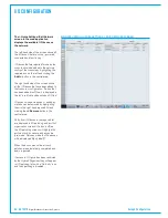
Select the
Network>Advanced
page
(Not the Network>IP Address>advanced
page). Click
Add
to add a new host to
the host table. Enter a name, eg 'Calrec-
Primary' and the IP address (or alternate,
aliased IP address) of the primary Calrec
card that the Perle will connect to.
Summary of Contents for Artemis
Page 5: ...calrec com Putting Sound in the Picture ARTEMIS INFORMATION...
Page 9: ...calrec com Putting Sound in the Picture ARTEMIS CONTROL SURFACE...
Page 26: ...26 ARTEMIS Digital Broadcast Production Console...
Page 27: ...calrec com Putting Sound in the Picture ARTEMIS PROCESSING CORE BEAM SHINE...
Page 33: ...calrec com Putting Sound in the Picture ARTEMIS PROCESSING CORE LIGHT...
Page 40: ...40 ARTEMIS Digital Broadcast Production Console...
Page 41: ...calrec com Putting Sound in the Picture ARTEMIS CONNECTION INFORMATION...
Page 66: ...66 ARTEMIS Digital Broadcast Production Console...
Page 67: ...calrec com Putting Sound in the Picture ARTEMIS EXTERNAL CONTROL...
Page 80: ...80 ARTEMIS Digital Broadcast Production Console...
Page 81: ...calrec com Putting Sound in the Picture ARTEMIS SETUP CONFIGURATION...
Page 100: ...100 ARTEMIS Digital Broadcast Production Console...
Page 101: ...calrec com Putting Sound in the Picture ARTEMIS PANEL OPTIONS...
Page 110: ...110 ARTEMIS Digital Broadcast Production Console...
Page 111: ...calrec com Putting Sound in the Picture ARTEMIS OBSOLETE PANELS...
Page 114: ...114 ARTEMIS Digital Broadcast Production Console...
Page 115: ...calrec com Putting Sound in the Picture ARTEMIS SPECIFICATIONS...