background image

126   ARTEMIS 

Digital Broadcast Production Console

Monitoring

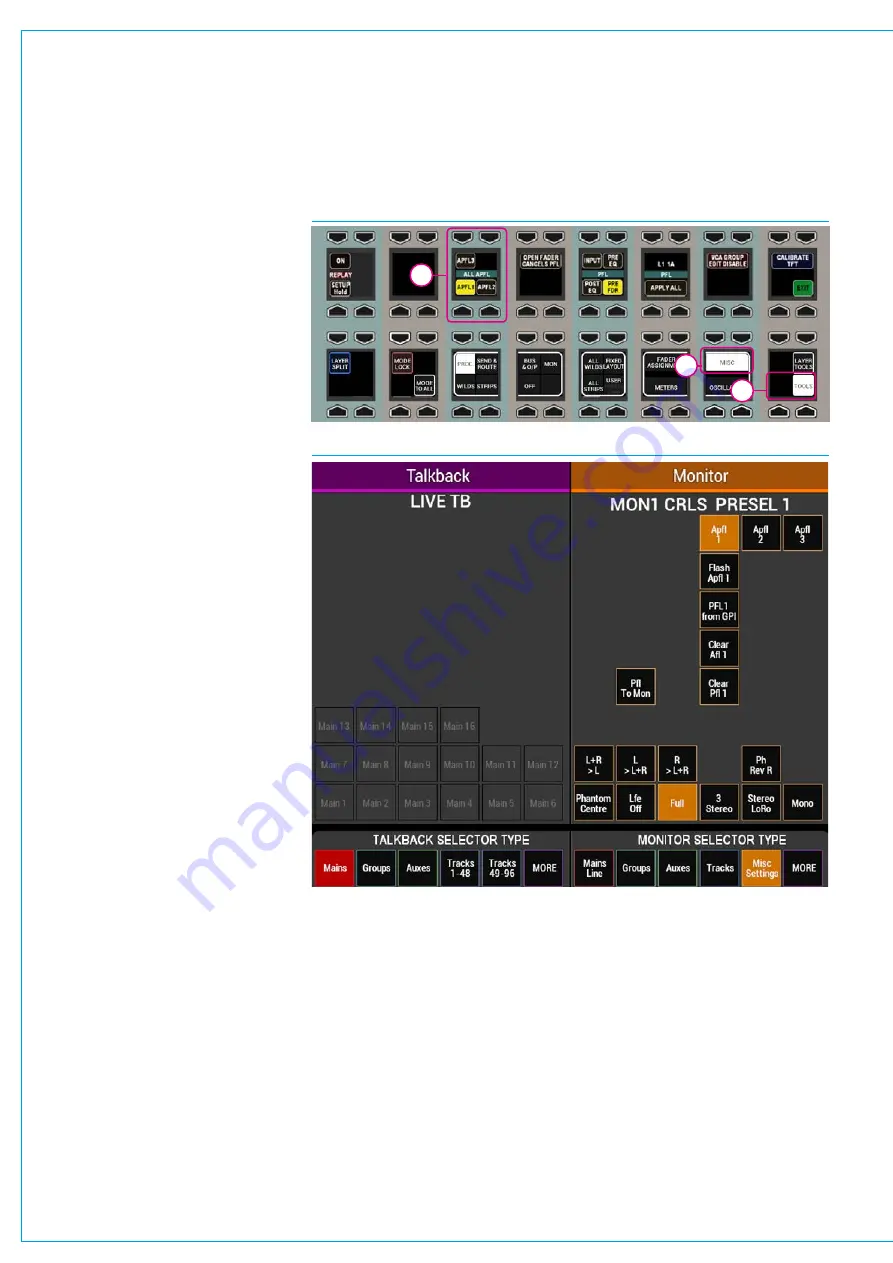
Select ‘Misc Settings’ from the monitor 
selector type menu at the bottom of the 
TFT screen to bring up monitor options 
and choose APFL 1, 2 or 3.  Use the 
control cell at the bottom left of the 
monitor mode panel to switch between 
Main Mon 1 and 2 and set their APFL 
system as required.

The ‘Flash APFL’ option for each APFL 
system instructs the APFL indicator in 
the broadcast facilities panel to flash or 
to illuminate steadily when any AFL or 
PFL is active in the relevant user section. 
If the option is selected, the indicator will 
flash.  If it is deselected, the indicator will 
illuminate steadily.  This allows two APFL 
systems on the same surface to have 
separate indicators, see Fig 8.

The ‘Clear AFL’ and ‘Clear PFL’ buttons 
clear AFL and PFL respectively for each 
APFL system, unless the PFL has been 
triggered by a GPI, see below for more 
information.

Note that if a path is moved to another 
fader on the surface or to another 
user split, the path’s AFL or PFL status 
will move along with the path, feeding 
the APFL system that has been set for 
that user split.

PatchAFL,PFLandAPFLbuses

As well as injecting into the main monitors, 
AFL, PFL and APFL systems are also 
available to patch to output ports.  APFL 
systems are available in monitor source 
lists, post their level controls and in meter 
lists, pre their level controls. 

PFLviaGPI

PFLs can be remotely activated via GPI. 
GPI-PFL selections are input port or input 
Alias based, firing the PFL of whichever 
path the input is patched to. 

 Se

“GPIO” on page 170

 for details on 

patching GPIs to surface functions.

If a channel’s PFL has been activated 
via a GPI, the EXT light next to the fader 
lights up green to indicate that control is 
being applied externally.

FIG 7 - APFL SELECTION FOR MULTIPLE USERS

FIG 8 - APFL INDICATOR OPTIONS

It is not possible to deactivate a GPI PFL 
from the desk, this can only be achieved 
by deactivating the GPI Opto itself. 

IfthePFLisonlyactivatedvia
GPI,theAPFLclearbuttoninthe
BroadcastFacilitiespanelwillnot
lightup.

In Monitor Mode, with ‘Misc Settings’, as 
shown above, there are ‘PFL from GPI’ 
enable buttons for each APFL bus.   

These can be used to quickly regain 
control of any channels which are set to 
have their PFL activated via GPI.  

For example for APFL 1, if a GPI has 
activated a channel PFL and you wish to 
deactivate the PFL from the control room, 
simply touch ‘PFL 1 from GPI’.  

Note that until this is reactivated the GPI 
PFL for all channels using APFL system 1 
will not work.

1

2

3

Summary of Contents for Artemis

Page 1: ...calrec com Putting Sound in the Picture Digital Broadcast Production Console ARTEMIS OPERATOR MANUAL Shine Ray Beam Light V8 2 ...

Page 2: ...ternational usage Calrec Audio Ltd reserve the right to change specifications without notice E O E The established policy of Calrec Audio Ltd is to seek improvements to the design specifications and manufacture of all products It is not always possible to provide notice outside the company of the alterations that take place continually Despite considerable effort to produce up to date information ...

Page 3: ...nd Route 31 Output Mode 32 Monitor Mode 33 Wilds Mode 34 Setting Up Wilds mode 34 Selecting Wilds 34 Wildable controls 34 Memorising Wilds 34 Assigning and Clearing 35 Memory Isolation 35 Alternate Fader Wilds 35 Wilds pages 35 Wildable Controls 36 Strips Mode 37 Accessing Strips mode 37 Apply to All Strips 37 Routing display 37 A B path indicator 38 Changing Strips types 38 Getting Signals Into A...

Page 4: ...isplay 72 Dynamics 1 73 Dynamics 1 controls 73 Processing order 74 Dynamics metering 74 Side chain EQ 74 About Dynamics Side chain EQ 74 Dynamics Links 74 Dynamics 2 76 Dynamics 2 controls 76 Automixer 77 Assigning control 77 Gain reduction metering 77 Delay 79 Assignable Delay at different sample rates 79 Individual Assignable Delay 79 Individual Path Delay 79 Delay Settings 80 Assigning Delay to...

Page 5: ...Direct Output Patching Shortcut 116 Monitoring 117 Monitor Mode 118 Control Room Monitoring 119 Pre selectors Favourites 119 Control Room speaker pre selectors 119 Changing pre selector source 119 Control room monitor controls 120 Loudspeaker cut buttons 120 Monitoring for multiple users 120 Monitoring at different sample rates 120 Dedicated Monitor Controls 121 Miscellaneous Monitor Sources 122 A...

Page 6: ...ode selected 164 System Reset 165 Fail warning indicator 165 Reset buttons 165 Technician Mode 166 Supervisors Technicians and Users 166 Accessing Technician Mode 166 Managing technician supervisor accounts 166 Exiting Technician Mode 166 Synchronisation Sources 167 Synchronisation at different sample rates 167 External Interfacing 169 GPIO 170 Assigning GPIs 170 GPI functions 170 Monitor Panel Cu...

Page 7: ...calrec com Putting Sound in the Picture ARTEMIS INFORMATION ...

Page 8: ...ighly static sensitive parts are exposed In order to protect these devices from damage and to protect your warranty please observe static handling procedures for example use an appropriately grounded anti static wrist band Calrec will supply an electrostatic cord and wrist strap with all of its digital products All modules and cards should be returned to Calrec Audio Limited in anti static wrappin...

Page 9: ...s Do not allow ventilation slots to be blocked Do not leave the equipment powered up with the dust cover fitted Cleaning For cleaning the front panels of the equipment we recommend using a soft anti static cloth lightly dampened with water if required Explanation of Warning Symbols Triangular warning symbols contain a black symbol on a yellow background surrounded by a black border The lightning f...

Page 10: ... and email Software and hardware upgrades Repairs Quick supply of replacement or loan hardware in the event of a failure Providing export documentation for the return of faulty parts On site commissioning visits On site service and health check visits Emergency engineer visits On site on air support for complete peace of mind providing operational guidance and technical engineering support for new...

Page 11: ...calrec com Putting Sound in the Picture ARTEMIS INTRODUCTION ...

Page 12: ...c EQ filters on each channel group and main path 2 x compressor limiters 1 x expander gate and sidechain EQ filters on each channel group and main path 4 independent simultaneous post fader pre fader or pre EQ track IFB sends per channel group path Up to 4 direct output mix minus sends per path Up to 2 73s of path delay per path I O Integral 8192x8192 router with up to 512 audio channels per Hydra...

Page 13: ...ls Input Delay Up to 2 73s per input from pool of 256 channels Up to 2 73s per input from pool of 128 channels Up to 2 73s per input from pool of 128 channels Up to 2 73s per input from pool of 128 channels Output Delay Up to 2 73s per output from pool of 256 channels Up to 2 73s per output from pool of 128 channels Up to 2 73s per output from pool of 128 channels Up to 2 73s per output from pool ...

Page 14: ... Input Delay Up to 2 73s per input from pool of 128 channels Up to 2 73s per input from pool of 64 channels Up to 2 73s per input from pool of 64 channels Up to 2 73s per input from pool of 64 channels Output Delay Up to 2 73s per output from pool of 128 channels Up to 2 73s per output from pool of 64 channels Up to 2 73s per output from pool of 64 channels Up to 2 73s per output from pool of 64 c...

Page 15: ... and recalled at show level The System Settings area contains the remaining functions that are stored at system level and do not change with shows The table in Fig 1 shows the Old and New names and locations of the various screens for reference purposes before and after the V6 0 release Misc Default Settings General Settings Inserts Setup moved to System Settings Meter Setup Meter Layout Mon Mtr E...

Page 16: ...ding via aliases for I O that is at a different sample rate to the desk Note these patches can be made in H2O and by SW P 08 and will work if patched there System Status messages are produced for I O boxes HPB that are in the required list but are not set to the same sample rate as the desk An I O box can run at 48kHz or 96kHz irrespective of which rack it is plugged into If a console is running a...

Page 17: ...calrec com Putting Sound in the Picture ARTEMIS CONTROL OVERVIEW ...

Page 18: ...ation is the main menu which contains buttons for each of the main sections of the application When this document instructs you to go to the Mem section for example it is the equivalent of saying touch the Mem button in the main application main menu Once a certain section has been selected a list of available screens will appear vertically along the left hand edge of the main application Touching...

Page 19: ...release without changing position See Fig 1 Multiple touches Hold and Touch In some cases it is necessary to combine touch controls to achieve the desired result One control will normally be held which touching other controls Fig 2 demonstrates this process This is normally only required between control cell displays on the surface Combinations between configuration PC and the surface will not be ...

Page 20: ...L CELL EXAMPLE When faced with a control cell with functions in the lower half only and a blank upper half it is a common mistake for new users to attempt to use the upper button rotary It is important to note that the upper part of the display relates to the upper rotary and button and that the lower portion of the display relates to the lower controls even if the upper portion of the display is ...

Page 21: ...rs Fader panels can be fitted without an associated upstand TFT panel if required however such panels would not provide access to some of the selectable panel mode functions A control surface with only one full fader panel and upstand TFT panel pair fitted gives full access to all control parameters by switching between panel modes however multiple panels are normally fitted to reduce the amount o...

Page 22: ... Fig 2 As well as selecting A B sub layers on a fader by fader basis the All A All B buttons located in the left hand button cell of the modes row will switch all faders unless user or layer splits are in place between sub layer A B In addition to A B sub layers there are a total of 12 fader layers each with an A B sub layer All layers and A B sub layers are active irrespective of which layer is c...

Page 23: ...mprehensive phase metering alongside other features such as loudness metering and stereo vectorscopes Please refer to the manufacturer s documentation for full details of the full feature set and configuration information Reset panels are also available without 3rd party meters Monitor Panel Monitor panels fit in the control bed and provides a dedicated set of monitoring controls As well as monito...

Page 24: ...l which provides all the controls available on that panel with the exception of Talkback Groups which appear on the fader panel in Talkback mode and additional Pan controls again which are available on the Fader panel in Send Route mode This was deemed to be an acceptable compromise given that this panel provides the additional 8 faders to allow a 72 fader bed on the console without a gap and stil...

Page 25: ...el on the console in the arrangement that you wish them to appear then press and hold the USER button The text on the button briefly displays SAVED to show that the process has been successful Press the USER button to recall the saved panel mode arrangements Fixed layout FIXED LAYOUT is a fixed arrangement of modes on the surface panels included to allow the user to return to a default layout Assi...

Page 26: ...nel will update to reflect values of the currently assigned path Assigning a different path will alter these displayed values Assigning a path Above each fader is a display and two buttons as shown in Fig 1 below The display shows the name of the A and B paths of each fader The upper section green shows the A path and the lower section yellow shows the B path The path that is currently being contr...

Page 27: ...feed one of three different APFL bus sets each of which can be patched to outputs for local monitoring and the two main monitors can be configured to be interrupted by different APFL sets allowing each user to be able to listen to their paths without affecting each other s monitoring Please refer to the monitoring section for details on configuring monitoring for multiple users See Monitoring for ...

Page 28: ... turned off This is currently a factory set option and Calrec should be contacted for activation With this option set the faders on the surface will only have access to one path per layer and can be accessed using the A layer path assignment buttons Layer selection is performed from the right hand side of the Modes row of any standard control bed panel as shown right If the layer select controls a...

Page 29: ...calrec com Putting Sound in the Picture ARTEMIS CONTROL PANEL MODES ...

Page 30: ...lay or output delay if on a bus Switch the insert on or off change stereo path width disable AutoFaders and override remote control Overview provides the essential controls you need to reach quickly If you need more detailed control change to the dedicated EQ Dynamics 1 Dynamics 2 Delay or AutoFader views by selecting them from the icon button cells at the bottom of the panel mode area which show ...

Page 31: ...le The TFT screen provides routing buttons and displays whilst the panel below provides colour coded rotary controls for send levels to applicable outputs such as Auxs Track sends and Direct outputs Pressing down on a rotary encoder highlights that send in the bottom row of controls providing further options such as pre fader post fader switching The last two columns of control cells provide pan c...

Page 32: ...el controls and cut buttons if applicable for each output bus Button cells in the bottom row allow for different groups of outputs buses to be viewed in the control cells above Pressing down on a rotary control highlights that output bus in the bottom row for additional controls such as listens tone and talkback selectors For Main and Group buses this area also includes an Assign button allowing t...

Page 33: ...de of the TFT screen allowing for the source to be changed and for miscellaneous settings to be applied The button cell to the left of the meter selectors allows for the panel to switch between controlling monitor output 1 and monitor output 2 See Fig 1 The button cell at the bottom left switches the left hand side of the TFT screen between talkback functions and a user memory load save screen see...

Page 34: ...ressing and holding two similar wild controls on the same row at the same time If the LINK WILD SELECTIONS button is selected any subsequent press of a wild control will select the entire row through all layers of the console and put them all into selected wild assignment flashing red Wildable controls The rotary control and button cells in wild assignment areas can be assigned to many controls in...

Page 35: ...he fader panel The selection will flash red From another console panel select any control from any panel mode On the original panel the chosen control assigns to the Wild control s Panel 1 Panel 1 Panel 2 Memory Isolation The Memory Isolation function includes the ability to prevent the wilds of any path from being overwritten when loading a memory To do this you must set the scope of memory isola...

Page 36: ...36 ARTEMIS Digital Broadcast Production Console Control Panel Modes WILDABLE CONTROLS ...

Page 37: ...ng the status of the MODE LOCK button also located on the Modes and Layers row The MODE LOCK button is always available even in strip type select mode allowing the user to switch between STRIPS mode and strip type select mode while locked to STRIPS Selecting STRIPS mode will display the last used strip type on the panel and show the available strip type buttons Apply to All Strips By default the u...

Page 38: ...he Modes and Layers row the available strips types are shown here Input Pan EQ Dynamics Aux 1 16 Aux 17 32 Track Sends and Direct Outputs To select an arrangement of strips touch the desired strip to assign it to the panel Touch the BACK TO MODES button to return to the typical Modes and Layers row display This process is illustrated in Fig 2 FIG 2 SETUP STRIPS ON THE MODES ROW Modes row in its ty...

Page 39: ...calrec com Putting Sound in the Picture ARTEMIS GETTING SIGNALS INTO ARTEMIS ...

Page 40: ... be changed to match In H2O a new button labelled Sample Rate is made available selecting this opens the list of I O boxes connected to the Hydra2 Network The list shown in Fig 1 shows the sample rate set for each I O box or Hydra2 Patchbay In order to change the sample rate the user first selects the required I O box or Hydra2 Patchbay box this enables the Set Sample Rate button at the bottom lef...

Page 41: ...put ports A port is a physical input to or output from the Artemis system As all I O is contained in a Hydra2 network each input socket on a Hydra2 box can be termed an input port Hydra2 Patchbays Virtual patch points can be created within the Hydra2 domain on a console by console basis using the H2O network administrator application Once configured in H2O Hydra2 patchbays appear as online in the ...

Page 42: ...ists go to the Hydra2 Settings Port Lists Labels screen see Fig 2 Select the Input Alloc or Output Alloc button at the left of the screen to work with input or output ports respectively The screen will show all available port lists just to the right of the Input Alloc button The Default List is created automatically and contains all available input or output ports Creating lists To create a new li...

Page 43: ...te to show the ports stored in the selected list Select the ports that are to be stored in a set and touch the Create Set button The number of the set will appear next to the ports The order of the ports within the set can be changed by selecting a port and touching the up or down arrow buttons Ports can be removed from a set by selecting them and touching the Remove From Set button Ports can be a...

Page 44: ...n be allocated to and controlled by faders The allocation of paths on faders is saved as part of the user memory Assigning channels to faders Selecting the Tools menu from the right hand side of the Modes row replaces the fader layer selection buttons with Tools sub menu selection buttons The selected sub menu is displayed in the row above See Figs 1 3 4 5 FIG 2 LABEL DISPLAYS FOR FADERS 1 4 In Fi...

Page 45: ... these faders ensure the panel is not in spill or Downmix mode Unlike input channels which are configured as they are allocated to faders the buses need to already be configured from the main application Operate Bus Config screen Please see the Buses Overview section for more detail Each numbered Main or group is a unique bus signal path If the same Main or group bus e g Main1 is allocated to more...

Page 46: ...and hold the CLONE FADER button from the LAYER TOOLS menu and then select the assign button of an unallocated fader that the clone is to be placed on Press EXEC to execute or CNCL to cancel the operation Faders for cloned channel paths indicate a clone icon in their label display to differentiate between clones of paths and separate channel paths that have the same input source patched See Fig 8 b...

Page 47: ... to Auxiliaries WILDS AUTOFADER ALL All of the above elements Note when copying settings which include assignable input and output delay the delay settings will only be copied if the destination already has the delay assigned The copy function is just for the delay setting not the delay itself To access the copy function push the LAYER TOOLS button and the row above will display the controls shown...

Page 48: ...same way as the patching screen This behaviour can be toggled in the States button in the left hand side of the footer of the main application FIG 1 MAIN APPLICATION OPERATE FADER SETUP SCREEN FIG 2 PATH WIDTH ICONS Mono Stereo 5 1 Surround Memories from larger consoles User shows memories can be transferred between mixing consoles of the same type for example an Artemis Shine User Memory can be t...

Page 49: ...u Destination types are listed in a column down the right hand side of this menu Highlighting My Desk Inputs displays the types of DSP inputs available to patch to clicking Channel I Ps closes the Available Destinations menu and displays a table of the control surface faders Channel input fader views When displaying channel inputs the right hand column of the destinations table and the text field ...

Page 50: ...estinations at different sample rates Port to port patches cannot be made for I O that is at a different sample rate to the desk However they can be made in H2O and by SW P 08 providing the source and destination ports are at the same rate Bulk patching and source views Multiple patches can be made at a time by selecting multiple cells For example selecting one source but multiple faders by click ...

Page 51: ... in the Select Sources menu Consoles can patch their DSP outputs to Hydra2 Patchbays which can in turn be patched as console sources allowing consoles to share their outputs across the network without using physical I O In addition to accessing other consoles outputs H2O network administrators and SW P 08 router controllers can patch Hydra2 Patchbays to from physical I O ports allowing them to rem...

Page 52: ...g shortcuts are available on the surface In the area at the top of the touch display in Processing mode INPUT PATCHING OUTPUT PATCHING and INSERT PATCHING buttons are available depending on the type of path accessed Tapping one of these buttons will change the main application to show the relevant patching screen show the appropriate source and destination lists and select the specific sources and...

Page 53: ... useful for diagnostics It s also possible to turn off dynamic labels received via SW P 08 or when showing the sources of Hydra Patchbays see Fig 8 Custom fader labels The Label column allows custom user labels to be shown in the fader s label display Double click on a cell in this column to enter a custom label Note that custom labels are associated with the fader rather than the input port The c...

Page 54: ...ckly switched between two inputs using the INPUT 1 and INPUT 2 selection buttons A common use for input 2 is for backup microphones allowing them to be easily available using the same fader processing and routing as when using the primary microphone on Input Mic Line gain The gain of any connected mic line input can be adjusted with this control The gain range varies from 78 to 18 dB This gain con...

Page 55: ...ording on the button cell changes to TRIMS LINKED to show that the process has been successful Adjustment of a linked input trim control will be applied to both Input 1 and Input 2 maintaining any offset between them FIG 2 INPUT SIGNAL FLOW Mic gain with 48V to L and R AES input with SRC Other inputs Input 1 trim Balance Stereo channel leg Mono channel leg To channel ø L ø R M S LTB RTB Input sele...

Page 56: ...reo path Switching both switches on sums the left and right portions of the signal together and outputs this on both the left and right legs With both switches in the same position either on or off you have access to the input balance control When they are both off the balance control responds as described above but with both controls switched on it is a full range balance control i e turning the ...

Page 57: ...l buttons can be accessed by selecting TOOLS and then MISC from the Layers row On the far left of the functions row above there are two buttons associated with Replay ON and SETUP Adding Paths to the Replay Set Paths can be added or removed from the Replay Set by pressing their ASSIGN button whilst holding the Replay SETUP button down as indicated in Fig 1 above Whilst holding down Replay SETUP no...

Page 58: ...trolling a Protected Input Port To alter a protected input Mic Gain 48v or SRC simply hold down the corresponding fader s assign button whilst making the desired change as usual Loading Shows Memory Alias Files There are implications for protected inputs Mic Gain 48v and SRC settings during the process of loading shows user memory and aliases for more information on memories see Using Shows and Me...

Page 59: ...efore being prompted to ACCEPT CHANGES again See Fig 3 Remember to ensure you know what the effect of the memory load will be before selecting ACCEPT CHANGES as this will alter the protected input sources for all operators The pop up in the main application may have 2 stages Input Sharing and Output Protection This indicates that the memory to be loaded also contains changes to outputs which are i...

Page 60: ...r is embedded into an SDI or MADI stream LED s A B C D on the front of the module itself illuminate green to show if decoder cards have been fitted in the four available slots on the module Passing signals through decoders Consoles with access to VO5873s will display the Dolby E decoders as I O ports available for patching in a similar way to regular I O patching Unless the I O lists have been cus...

Page 61: ... regular I O ports To put them on input channel paths choose My Desk Inputs from the Select Destination menu or to pass the decoded audio straight out they can also be patched directly to output ports of any format See Fig 2 on the previous page Like other input ports the feed from the decoders can be patched to multiple destinations simultaneously Important sample rate conversion In order for a D...

Page 62: ...ailable input ports are shown in the right hand window and can be placed as part of the alias by touching the Add Ports button Once added the ports can be given a function related name as shown in Fig 1 The commonly used CTRL X CTRL C and CTRL V for cut paste and copy can be used to speed the entry of text names Names must all be unique and any temporary duplicate is shown with a red warning Once ...

Page 63: ...ng that may be in use on a console Alias mic bus Alias Mic Bus allows the ports to be assigned to one or more of the console s five mic open buses so that studio speaker muting is correctly assigned when the production changes studios Enabling an alias file To make an input alias file active and ready for use go to Inputs Active and using the arrows placed the required file s into the left window ...

Page 64: ...es a Tone selector Changing the mode of panels or the assigned focus by selecting a different fader or output bus does not clear the tone Tone will remain until deselected or globally cleared FIG 2 OSCILLATOR CONTROLS The Oscillator functions provide control over internal tone parameters and allow the option to override the internal tone generator with external or house tone These controls can be ...

Page 65: ...le if 1kHz can be heard anywhere other than front L R there must be a problem with routing or patching External Tone The EXT MONO EXT ST and EXT 5 1 buttons override the console oscillator allowing for externally generated tone to be applied for users who have a house tone ident system Mono Stereo and 5 1 tone paths are separated to support their idents External tone can be applied and selected in...

Page 66: ...at buses LoRo LtRt outputs at the same level This is because tone is being applied at the final output stage With tone to line selected the signal on LoRo LtRt is NOT derived from a Downmix or encoding of the surround channels The same level of tone is applied to both the 5 1 and the downmixed output Tone on stereo downmixed encoded outputs higher than expected If tone is fed from a surround chann...

Page 67: ... Consoles can patch signals to their own or shared Hydra2 Patchbay inputs in the same way they patch to physical output ports FIG 1 HYDRA2 PATCHBAYS Hydra2 Patchbays allow network administrators via H2O to patch console inputs and outputs which have been patched to Hydra2 Patchbay ports to physical I O ports H2O users can choose physical input ports to connect to console s Hydra2 Patchbay inputs a...

Page 68: ...ands the contents of the Input Output protection dialogue before accepting any changes as these changes directly affect other network users Console operators are given the ability to change the source feeding a HPB that is feeding other consoles to add increased flexibility However we advise that all I O box port to Hydra2 Patchbay input patching is controlled from H2O or a third party controller ...

Page 69: ...calrec com Putting Sound in the Picture ARTEMIS PROCESSING AUDIO ...

Page 70: ...ocessing Audio CHANNEL SIGNAL FLOW Fig 1 below illustrates the signal flow in an Artemis channel path showing how Inserts EQ Dynamics Path Delay and the relevant send and output points can be positioned within the signal path FIG 1 CHANNEL SIGNAL FLOW ...

Page 71: ...e in greater detail These controls only affect the currently assigned path On Off Buttons in the column next to the Trim input control cell switch all bands 1 4 on or off together and bands 5 and 6 on or off together A B alternate EQ Settings Two EQ curves can be created per channel using the EQ Settings A B buttons on the TFT screen Tapping these flips between the two EQ curves for quick EQ chang...

Page 72: ...s as the Q control Fig 2 shows the Response Types and parameters EQ curve display The TFT touchscreen above the Control cells shows a graphical representation of the current EQ curve for the assigned channel with it s band markers numerical values and response type Note that a thumbnail view of the EQ curve is also made available in the PROCESSING EQ button cell selector RESP Gain Range Q or dB oc...

Page 73: ... Frequency and Q Response types The TFT screen displays a graph of input level versus output level along with switchable gain reduction meters the position of the Dynamics 1 processing in the signal path and switches for control and gain reduction independence of legs for stereo and 5 1 path legs With SCEQ selected on the TFT screen it also displays the EQ curve for the dynamics 1 side chain Also ...

Page 74: ...ing SCEQ ON from the TFT screen on the left of the EQ curve or from the panel as described About Dynamics Side chain EQ All Dynamics 1 processors have optional side chain EQ Channels have 2 bands of SCEQ whilst Groups and Mains have a 1 band of SCEQ The side chain is an offshoot from the audio path through the Channel Group Main outputs Dynamics processors use the side chain to determine the audio...

Page 75: ...0 1 35 1 40 1 50 1 Limiter Attack 50µs to 200ms 5ms default Make Up Gain 0dB to 20dB Expander Threshold 10dB to 40dB Recovery 75ms to 4s Auto Depth 0dB to 40dB Ratio 2 1 and Var variable according to level Attack 300µs fast 16ms normal FIG 2 DYNAMICS PARAMETERS Gate Threshold 0dB to 40dB with 6dB hysteresis Recovery 75ms to 4s Auto Depth 0dB to 40dB Attack 300µs fast 16ms normal Gate Delay 0s to 1...

Page 76: ...or Limiter controls for ON Threshold Ratio Attack Recovery and Gain Make up The TFT screen displays a graph of input level versus output level along with switchable gain reduction meters the position of the Dynamics 2 processing in the signal path and switches for control and gain reduction independence of legs for stereo and 5 1 path legs Note in this image a Mono Path is being displayed so no in...

Page 77: ...ese only appear on Mono paths if the path is not currently assigned to an Automixer or Dynamics 2 side chain link the No Link button will be lit Select the other faders that need to be in the same automix group and assign them to the same automixer number To clear a path from automixer control and side chain links select No Link from the Dyn Links area on the TFT screen To place the path under the...

Page 78: ...s from that input e g to give more emphasis to a presenter over guests when they are talking at the same time As an example if only one fader within an automixer group has audio content no gain reduction is applied to that input and its automix meter will display full 0dB If only two faders have audio and the audio is at the same level e g tone for test purposes 6dB of gain reduction is applied to...

Page 79: ...mono legs worth of delay becomes 128 mono legs of delay for Artemis Shine however the amount of delay per leg remains unchanged at 2 73s Note that for Artemis Ray Beam Light these figures are 128 mono legs at 48kHz and 64 mono legs at 96kHz Individual Assignable Delay To apply an assignable delay select the PROCESSING DELAY panel mode and press the appropriate assign button Input or Output on the ...

Page 80: ...ous page for the Delay processing mode Assigning Delay to a Faderless Path To assign Delay to a path which is not assigned to a fader put a panel into OUTPUTS mode and press on the rotary controller associated with that output This brings up the selected bus controls within the Fader row on which there is an assign button Press this assign button and then assign delay in the usual way from any sur...

Page 81: ...o through stereo through to wide Wide creates an apparent extension of the image past the usual left and right limits Stereo width appears pre fader post EQ and dynamics in the processing chain and it s rotary control and ON switch appears on the PROCESSING OVERVIEW panel mode It must be switched in circuit using the ON button in the 4th Control cell top row as shown in Fig 1 FIG 1 STEREO WIDTH CO...

Page 82: ... of fader controls are for front Left Right the second set for the Centre channel the third set for the LFE channel and the fourth set for the rear Ls Rs channels In spill mode with a stereo path selected the first two faders control the left and right channels PFL AFL buttons allow each element to be listened to pre and post fader The faders themselves allow for the level that each element output...

Page 83: ...und spill element assigned The independence over dynamics settings for the assigned surround element are switched for gain reduction independence and control of legs for stereo and 5 1 path legs on the PROCESSING DYNAMICS mode TFT screen By making the dynamics gain reduction independent for a given leg that leg will only have gain reduction applied when it crosses the threshold itself The control ...

Page 84: ...serts at different sample rates From version 8 0 the desk can be configured to operate at different sample rates such as 48kHz 96kHz At the higher sample rate the pool size for inserts is halved meaning that the pool of 256 mono inserts becomes 128 mono inserts Note that for Artemis light these figures are 128 mono inserts at 48kHz and 64 mono inserts at 96kHz The image in Fig 2 shows the Insert s...

Page 85: ...an be assigned to lists Lists provide a way of filtering the insert resources and can be selected when patching insert resource sends and returns to ports or connecting insert resources to paths To access insert resources lists go to the Inserts Setup screen in the Show Settings section of the main application Select the Insert Alloc button at the left of the screen The screen will show all availa...

Page 86: ... insert resources from lists To remove resources from a list select the required resources and touch the Remove Inserts button Renaming lists Touch the Modify Lists button to bring up a popup dialogue This dialogue allows you to select a list and rename it Removing lists To remove a list select the required list and touch the Remove List button A popup dialogue will appear asking for confirmation ...

Page 87: ...its slaves changes by the same amount Its adjustment will not affect the level of the primary master or its slaves Changing the CUT AFL or PFL of a secondary master applies the settings to the secondary master s slaves only Fader status indicators Each fader contains two indicators next to each assign button as shown in Fig 2 Neither indicator will be illuminated if the fader is not part of any VC...

Page 88: ...trobe the intermediate s assign button slowly and the intermediate s master s assign button quickly While holding an assign button only the assign buttons relevant to the VCA group will illuminate or strobe The rest will be unlit for clarity Masters slaves on the same fader Masters can be created on a faders which do not contain a path They can also be created on faders which already have a path a...

Page 89: ...nd Hold this button to trigger the Autofader and release to release the Autofader This button allows the user to walk through the action of the Autofader and adjust parameters if necessary IN LEVEL This is the level that the fader goes to when the GPI is triggered shown as an IN line OUT LEVEL This is the level that the fader goes to when the GPI is released shown as an OUT line FADE IN DELAY This...

Page 90: ...h groups of available functions that can be controlled by the GPIs Select AutoFader to populate the right hand side of the screen with the available autofaders A single GPI may control any number of autofaders so assignments can be made one to one or one to many Select the required GPI from the list on the left and any number of autofaders from the right Now touch the Patch button To remove a conn...

Page 91: ...I is currently triggered the audio should fade up or down to the Fade In Level if it is not there already complying with the Fade In Duration parameter rather than snapping the audio to the Fade In level When the trigger signal is present the fader will follow the settings made on the PROCESSING AUTOFADER screen Autofader parameter settings The AUTOFADER screen allows the settings of the autofader...

Page 92: ...go to their specified or expected On or Off level first Fade in and fade out values are absolute in that the time taken from the beginning to the end of the fade in or fade out period lasts for the duration set by the relevant control regardless of the actual physical starting level that may have been manually set and differ to that of the AutoFader s set On Off level If a fader is positioned at o...

Page 93: ...calrec com Putting Sound in the Picture ARTEMIS ROUTING AUDIO ...

Page 94: ...sted which in the case of auxiliaries on an Artemis Shine Ray or Beam at 48kHz is 1 32 For each of these the width can be defined by selecting the relevant row or rows and choosing the desired width from the buttons on the right of the screen At the top of the screen a number shows the remaining mono DSP resources for that bus type When this number reads zero no more buses may be created unless mo...

Page 95: ...ing the outputs that are independently cut depending on the status of each path routed to the aux output For example if Pre Fader Send cut when fader closed is selected for Aux output 1 the pre fader sends from each path routed to Aux1 will be muted whilst their fader is closed FIG 4 MAIN APPLICATION OPERATE BUS CONFIG AUXS SETUP SCREEN As soon as the fader is opened the path will send audio to th...

Page 96: ...s it the focus of the central five button cells at the bottom of the panel Aux Send 10 is the focus in this image These 5 button cells highlighted below provide access to positional controls such as pre post fader and on off switching Paging Through Buses Given the finite size of the touchscreen and number of available control cells it may not be possible to view all required buses at once In this...

Page 97: ...destination bus type on the touch screen strip The strip will be populated with larger routing buttons of the selected type which can be touched to create or remove routes As with the overview it may not be possible to fit all possible routing destinations on a single page The destinations can be paged through either by using paging buttons similar to the overview screen or by swiping the screen u...

Page 98: ...ing a mono path to a mono bus there will be no controls available When sending a mono path to a surround bus a great deal more controls will be presented that allow control over mono placement in a surround field The complete range of controls is described here Front Pan Front pan allows positioning of the signal in the L and R speakers The button next to the Front Pan rotary control switches the ...

Page 99: ... the joysticks can control to be selected by pressing SEL USER All other controls in the area shown including the rotary pan controls and the joystick itself are inactive and cannot affect the currently selected path unless CONTROLS ACTIVE is selected from the bottom left Making the joystick controls active When the required path has been assigned the joystick controls must be made active To do th...

Page 100: ... more information on accessing the elements that make up a surround path see Stereo Surround Spill on page 82 Pan control menu The button cell at the top left of this section contains the PAN CTRL menu These controls allow for the left right and front rear pans to be switched in as do the buttons alongside the rotaries The PAN CTRL menu also allows for the front L R pan to be switched to L C R cre...

Page 101: ...screen containing the text View Bus Contribution touching this area will switch the screen into the No Bus Selected configuration screen as shown in Fig 1 above right When the screen is switched to bus contribution mode tap to select any destination that you wish to interrogate If a path on the current layer is routed to the selected main group track aux or mix minus bus it s path assign button wi...

Page 102: ...ers are informed of routes made from other user areas by notification in the top central contribution box as in Fig 5 which shows Track 1 on the contribution screen which is being contributed to from User 2 While in contribution mode routes from multiple paths to the selected buss may be made or removed by pressing the relevant path assign buttons The path assign buttons will strobe if the route i...

Page 103: ...this Note When viewing bus contribution to Mains Groups Tracks or Mix minus the faders will always display the channel or group path level and the Fader Aux send message is removed from the fader display If the channel or group path on a fader is not routed to the selected destination or no valid path exists the fader will move to the off position and have no contribution to the selected destinati...

Page 104: ...ns button in the dialogue box that will also change the default send position for all new paths to that set by the selected send position See Fig 9 above right Mix Minus Bus Contribution Fig 10 right shows the Contribution screen for the Mix Minus Bus This is the only Mix Minus bus currently in the system and is routed to in the same way as the other buses This bus can also have its default send p...

Page 105: ...m of the panel This enables access to a wider range of controls for that specific send such as pre or post fade Removing sends If a channel has been routed to a track using send C then send C must be selected when removing the route Only routes made with the currently selected send may be removed In order for the track routing to be collapsed back into just one send all routes from sends B C and D...

Page 106: ...tain stereo separation by mixing front L rear L C together to create a LO Left Overall channel and front R rear R C together to create a RO Right Overall Default downmixes do not include the LFE channel but this can be added if required The levels that the surround elements mix together to form a downmix are defined by the downmix set Default downmix values are applied console wide As well as the ...

Page 107: ...e console is fitted with a full featured dedicated monitor panel With a surround path assigned selecting the DOWN MIX LEVELS mode using the button located beneath the second fader on the monitor panel changes the faders to reflect the contribution made from each element of the surround path to a downmixed feed Unless previously adjusted on that path the faders should show the levels as dictated by...

Page 108: ...l 5 1 Note when a main output is set for Lt Rt only the downmix audio patched to output ports is phase encoded Any internal routing of the surround main output to stereo destinations remains as LoRo For example if a surround Main 1 bus is routed on to stereo only Main 2 bus or if a full surround bus is being monitored in stereo i e the chosen source is full 5 1 but the monitor is in stereo mode Fi...

Page 109: ...calrec com Putting Sound in the Picture ARTEMIS PASSING SIGNALS OUT OF ARTEMIS ...

Page 110: ... desk However they can be made in H2O and by SW P 08 and will work if patched there providing the source and destination ports are at the same sample rate Patching Shortcuts Note that the Patching Shortcuts described earlier equally apply with output patching as they did with input patching See Patching Shortcuts on page 52 Hydra2 Patchbays Virtual patch points can be created within the Hydra2 dom...

Page 111: ...nd deselects all patching changes as a whole On clicking Accept Changes changes which are checked in the pop up plus any changes which are not displayed due to them having no effect on protected outputs are all made and the pop up closes On clicking Cancel All all changes that affect protected outputs are rejected but all changes which do not affect protected outputs are made and the pop up closes...

Page 112: ...the left and right of the panel Accessing further controls Four of the button cells at the bottom of the panel are used for more detailed control over the currently selected output To select an output push down on the relevant rotary control The current selection is indicated by the colour of the four button cell displays and also by a text label which spans across the centre of them Controls that...

Page 113: ...ned to more than one of a buses outputs Link buttons appear to allow the controls to track together Select each output to the same link bus in order for the delay control to track on all when any of them are adjusted Linked delay can be offset if delay is adjusted before linking the difference in delay values is retained after the link is made the controls will track together whilst maintaining th...

Page 114: ...ader on the surface See Fig 1 Tone to mains When controlling main paths the buttons above each fader that performed the CUT or ON functions for spill levels now inject tone into the relevant main output The hidden till lit indicators will confirm this function Accessing Spill controls for Main faders When controlling main paths and a main path on one of these faders is assigned it is not possible ...

Page 115: ...t to setup the direct output 2 Place any panel into SEND ROUTE mode The four centre right control cells will read Push to add Direct Output see Fig 1 Push one of these cell s rotary encoders and the Direct Output pop up appears on the TFT above as shown in Fig 2 3 Select mono or stereo to enable a Direct Output and select either a feed position Pre EQ Pre Fader or Post Fader or choose to have the ...

Page 116: ...e panel s TFT Alternatively find the same screen on the main application from the I O I O Patch Select Source Direct Outputs and click on the output cell for the required fader To switch in and adjust delay access the PROCESSING DELAY panel see Processing Delay on page 79 As with input delay and bus output delay the value can be displayed in either milliseconds or video frames The control area on ...

Page 117: ...calrec com Putting Sound in the Picture ARTEMIS MONITORING ...

Page 118: ...can be set into Monitor mode providing controls for monitoring metering and talkback features Fig 1 shows the layout of controls in monitor mode To set a fader panel into monitor mode touch the MONITOR button on the Modes row MONITOR MODE FIG 1 CONTROL LAYOUT IN MONITOR MODE ...

Page 119: ...the triangular HEAR indicator in the lower right hand corner of each pre selector makes that the chosen source to be fed to the control room speakers Changing pre selector source The right hand side of the fader touch screen displays the available sources which the user can set to a pre selector This is also shown in Fig 1 Tabs at the bottom of the screen allow different types of paths to be shown...

Page 120: ...g across the centre of the display This allows for 2 operators using the same processing rack either on the same surface one of the monitor outputs could be patched to a headphone feed or using extended surfaces or sidecars to have their own set of monitoring controls either from dedicated monitor panels or from assignable mode panels If user splits are also in place to demarcate sections of fader...

Page 121: ...e cells is determined by the Misc Mon TB In the right hand button cell display above the Level control The MON SEL button cell bottom left allows the user to listen to any of the four control room monitor pre selectors The pre selectors cannot be defined on this dedicated monitor panel this must be done in monitor mode using the Pre selectors The TB GROUPS button cell bottom right allows the user ...

Page 122: ...ols are also available on the Fader Monitor panel see Monitoring on Fader Monitor Panel on page 123 Alter the output source The output source can be altered by pressing the SEL button which brings attention to the required miscellaneous output on the TFT screen in Monitor mode Now press on the new source in the right hand side and the control cell display will update to show the newly selected out...

Page 123: ... is the Mon2 CRLS button which changes the large main Monitor control below between Mon 1 CRLS and Mon 2 CRLS The right hand column contains AFL Trim and PFL level control cell Small LS level with Large Small LS C O switch and Dim level switch control cell Below these is the MON SEL button cell which provides upto 4 different monitor source selections for frequent use At the bottom of the monitori...

Page 124: ...tons Both are either latching if tapped briefly or momentary if held By default PFL is automatically cancelled when a fader is opened e g if a fader reaches whilst PFL is activated PFL will be deactivated when the fader reaches 90dB This feature can be disabled by turning off the OPEN FADER CANCELS PFL button within the TOOLS MISC menu PFL can also be activated using the fader overpress feature Mo...

Page 125: ... select the required source and destination ports and push the Patch button Send PFL to the small LS The system can be configured to route PFL signals to the small loudspeaker overriding any other signal presently going to it This is a factory defined configuration and should be specified when the console is ordered FIG 6 MONITOR PANEL MODE PFL TO MON INPUT INSERT DYNAMICS EQ WIDTH INSERT DYNAMICS...

Page 126: ...nto the main monitors AFL PFL and APFL systems are also available to patch to output ports APFL systems are available in monitor source lists post their level controls and in meter lists pre their level controls PFL via GPI PFLs can be remotely activated via GPI GPI PFL selections are input port or input Alias based firing the PFL of whichever path the input is patched to See GPIO on page 170 for ...

Page 127: ...mally be fed from Hydra2 output ports allowing the headphone feed to be selected from the control surface Please consult with your installation engineer if unsure of connectivity Patch the headphone output Navigate to System Settings Fixed I O shown in Fig 2 In the sources list on the left press the filter button and select Monitor Outputs From the list select any monitor output you wish to drive ...

Page 128: ... and right signals to the left speaker L L R and R L R send the left and right signals to either the left speaker or right speaker respectively Ph Rev R reverses the phase of the right speaker Phantom Centre mutes the centre speaker and sends the centre information to the left and right speakers to create a phantom centre image Lfe Off mutes the Lfe signal to the speakers Full sends the full surro...

Page 129: ...tatus of the external unit via GPI tallies and indicators on a fader panel To enable a monitor insert use the main application and go to System Settings Fixed I O and touch the Select Source button then choose Monitor Outputs in the Desk Outputs column Then touch the Select Destination button and filter that to confirm the port to be used as the insert send typically an AES port on a BNC connector...

Page 130: ... the screen provides mode selection for the chosen unit The modes can be chosen by touching on the buttons which illuminate to show the current status It should be noted that whilst the SDU4 uses latched outputs from the console the DP570 and DP564 only show status information as returned by signals from the encoder decoder units The control outputs and tally inputs are via the console s GPIO syst...

Page 131: ... monitor system 1 of the console using simple and familiar monitor controls When Enabled the user must set the width of External Input 143 to 5 1 and the width of External Input 144 to stereo for 5 1 2 or to 5 1 for 5 1 4 The normal 5 1 legs of the 5 1 x render must be connected to External Input 143 and the 2 or 4 height legs must be connected to External Input 144 The user can label the External...

Page 132: ...132 ARTEMIS Digital Broadcast Production Console Monitoring ...

Page 133: ...calrec com Putting Sound in the Picture ARTEMIS COMMUNICATIONS ...

Page 134: ... to allow multiple talkback destinations to be fed simultaneously with a single button press These group controls are located in the middle row of control cells at the left hand side of the panel and are also repeated on the monitor panel To set talkback group destinations press and hold the upper SEL button in the relevant control cell then tap the required destinations on the touchscreen To togg...

Page 135: ...ttings When a microphone is patched to a talkback input the mic may be provided with phantom power analogue inputs or SRC applied AES3 inputs by checking the relevant box see Fig 3 To adjust the mic gain touch the relevant Analogue Gain cell to bring up a dialogue for selection of the desired gain Monitoring reverse talkback signals To monitor reverse talkback inputs the RTB bus must be patched to...

Page 136: ...or presenters in studios communicating via long distance systems such as satellite links The reporter would need to hear a mix of the show s audio in order to hear cues and communicate with the presenters The inherent delay in these systems means that it may be a number of seconds before the audio reaches the reporter It can be very difficult to speak while hearing your own voice returned to you w...

Page 137: ...ts from the popup that appears Select the fader where the source that is to be fed the mix minus signal appears Press the Select Destination button and select from the lists of output ports Select an output port and then press Patch For more details including how to allocate direct out resources please see Direct Outputs on page 115 Monitoring a mix minus signal Assign a path on the surface that i...

Page 138: ...138 ARTEMIS Digital Broadcast Production Console ...

Page 139: ...calrec com Putting Sound in the Picture ARTEMIS METERING ...

Page 140: ...eters of half two thirds or the full height of the screen A vast range of meter cell designs can be created but some arrangements have specific advantages For example using 2 meter cells across the width of each vertical section will give 8 meters across the TFT screen This allows meters to line up with the faders on the fader panel below Meter Grid Configuration Select Show Settings Meter Layout ...

Page 141: ...ttons down the left hand side populates the main window with all available meter source options of that type Some meter sources have sub options such as choosing a loudness meter or an A B fader path meter Once you have selected a meter source touch Apply to selected to add that meter source and function to the selected meter cell Alternatively Apply to end of row sets the selected cell to the ass...

Page 142: ...atively A B layer meters can be chosen which follow the currently active layer for the path on the surface The labels under each meter display the fader label port description and port name in priority depending on which have been set Meter Layout Presets From V6 0 the data structure for Metering files has been altered and each show now contains its own meter layout Just as with Path Presets you c...

Page 143: ...source Selecting a meter selector to display on the upstand TFT is done as normal from Show Settings Meter Layout MTR1 4 are located within the Other Meter source menu Patching the meter selector output to an audio output is done from System Settings Fixed I O then select Ext Meter Outputs from the Select Source list Meter selectors are available in the lower button cells when in the Monitor panel...

Page 144: ...ply by pressing a selection button from the TOOLS METERS menu See Fig 1 Change multiple fader meters by holding the selection down and then selecting the desired faders by pressing their fader assign buttons Press and hold APPLY ALL and then choose a signal path point selection to change all fader meters across the surface or within the user split The meter s label will display the point from whic...

Page 145: ...elect Source button at the top of the screen and choose Ext Meter Outputs from the popup window that appears Find the port to which the external meters are connected in the list of ports on the left of the screen If you are unsure where any meter are physically connected contact your installation technician With the destination port selected choose a source to feed the meter and then touch the Pat...

Page 146: ...splaying EBU mode with 9 18 LU scale Loudness meter modes relate to standards set by organizations in different geographical regions EBU European Broadcasting Union relates to Europe ATSC Advanced Television Systems Committee to North America and ARIB Association of Radio Industries and Businesses to Japan These are currently the main standards and are being widely adopted in other geographical re...

Page 147: ...Start Loudness Meter Pause Loudness Meter Reset Loudness Meter Loudness meter controls shown within the fader row and the bottom row of the fader panel Scale Target Loudness Target Variance Max True Peak Relative Gate EBU Mode 9 18 LU EBU 9 relative 18 36 LU EBU 18 relative 14 41 LUFS EBU 9 absolute 5 59 LUFS EBU 18 absolute 0LU 23 LUFS 1 LU 1 dBTP 10 0 LU ATSC A 85 2011 BS1770 1 9 18 LU 9 relativ...

Page 148: ...148 ARTEMIS Digital Broadcast Production Console ...

Page 149: ...calrec com Putting Sound in the Picture ARTEMIS SHOWS MEMORIES AND PRESETS ...

Page 150: ...150 ARTEMIS Digital Broadcast Production Console Shows Memories and Presets OVERVIEW FIG 1 SHOWS USER MEMORIES ACTIVE OPTIONS FILES AND CONTINUOUSLY SAVED CURRENT SETTINGS ...

Page 151: ... be used as a template for customisation and variations can be saved with different names New shows that are similar to existing ones can be created by choosing to Save Show As This effectively makes a copy of the show including the user memories within so that it does not have to be built from scratch Any unwanted user memories within the new show can then be deleted In addition to the settings t...

Page 152: ...isplays the memory selected if any from the available memory list This is the memory that will be loaded if the Load button is pressed and the default save overwrite location if the save button is pressed Shows and memories are saved on the controller card in the console s processing rack Note the Capacity Used bar meter below the memory list shows the amount of space available on the controller c...

Page 153: ...AIN APPLICATION MEM OPEN SHOW SCREEN Creating and editing default shows Users logged in to the main application as technicians from the Tech screen have the ability to convert or save existing shows as defaults making them available as templates for new show creation Selecting Convert to Default removes the show from the Open Show list and places it in the New Show templates list The Save Show As ...

Page 154: ...taining the show files Highlight the required show file s from the Backed Up Shows list in the lower portion of the screen and then press Restore Renaming shows The Mem Backup Shows List screen can be used to rename show files located on the console Highlight the desired show in the console show list and press Rename Show Deleting shows Show files can be deleted from the Mem Backup Shows List scre...

Page 155: ...ot backed up individually but as part of the show See backing up shows and memories on the previous page Ordering the memory list The order in which memories are displayed within the list can be filtered by any of the columns by clicking on their headers A small arrow next to the column header label shows the current filtering Click on the Memory Label header to ensure they are in alphabetic order...

Page 156: ... the screen The Update Mem button at the bottom of the screen can be used to overwrite any memory in the cue list with the current settings on the control surface Note this does not replace the cue with a new memory as with New Cue New Cue with new Memory instead it overwrites the memory location being addressed by the cue This is in essence the same as saving the memory from the standard Shows Me...

Page 157: ... 16 20 24 42 E C 60 DYN O P 1 PATH MR SL MR SL 20 PEAK 40 0 60 50 5 20 30 10 5 0 10 0 20 10 10 START ON 0 STRIP FDR CUT ON AUTOM EXT CUT AFL ISO DIR TB PFL 4 8 12 16 20 24 42 E C 60 DYN O P 1 PATH MR SL MR SL 20 PEAK 40 0 60 50 5 20 30 10 5 0 10 0 20 10 10 START ON 0 STRIP FDR CUT ON AUTOM EXT CUT AFL ISO DIR TB PFL 4 8 12 16 20 24 42 E C 60 DYN O P 1 PATH MR SL MR SL 20 PEAK 40 0 60 50 5 20 30 10...

Page 158: ...ory isolate mode as shown in Fig 4 apart from the mode title the TFT screen appears blank in this mode The lower two rows of control cells on the fader area will now display the elements of the path which can isolated They relate to the currently assigned path These elements may vary depending on the type of path assigned for example input and input port settings are not applicable to groups Press...

Page 159: ...solation Input 1 Settings Input 1 Ports Input 2 Settings Input 2 Ports EQ Bands 1 4 EQ Bands 5 6 Dynamics Unit 1 comp lim exp gate Dynamics Unit 2 comp lim Insert Fader Level and Settings VCA Master Fader VCA Slave Downmix Stereo Width Path Delay Pan to Mains and Groups Routing to Mains and Groups Track Send Levels Pan Track Routing Aux Send Levels and Routing Mix Minus Routing Direct Output Level...

Page 160: ...icon as an indication that it is now isolated Repeat the process to remove the isolation Improvements to Memory Isolate System From V7 0 Mains Auxes and Tracks can now be isolated in the same way as Channels and Groups From V7 0 when a bus is patched to a destination and that destination is isolated the width of the relevant bus is also isolated This prevents an incoming memory from changing the w...

Page 161: ... the folder you wish to save the preset making a new folder if necessary 3 Tap NEW 4 Select the scope of parameters that will be recalled when you load the preset these can be changed later and choose NEXT 5 Enter a label and description then tap OK Loading a Preset To load a preset to the currently assigned path 6 From either the Processing panel mode on the panel touch screen next to Current Ass...

Page 162: ...be created from the Select Backup Location dialogue Presets can be backed up individually or in multiples Select the preset s to backup from the upper list by clicking on them to highlight Press the Backup button to copy the selected preset s to the desired location Note that if the presets menu on the TFT is open then the Backup function will be unavailable Restoring Presets Previously backed up ...

Page 163: ...calrec com Putting Sound in the Picture ARTEMIS CONSOLE FACILITIES ...

Page 164: ...strictions Talkback to main outputs is disabled All other talkback dims control room loudspeakers All tone is disabled It can also be used to control an external interface such as an On Air light in the studio via the console s general purpose outputs In this case when the console was switched into On Air mode the restrictions would be put in place and the On Air light would be lit Rehearse The Re...

Page 165: ...d Reset buttons Buttons on the Central Meter panel allow the DSP surface and control systems to be individually reset To do this hold the appropriate button for the failed component and then press the ENABLE button as shown in Fig 3 below Similar buttons are also available on the rack with the addition of the Hydra2 Router reset button Be extremely cautious when resetting the Hydra2 Router Expande...

Page 166: ... supervisor or technician account and touch the OK button If this is the first time that technician mode has been accessed or no supervisors have been configured yet you will be prompted to create a supervisor account by entering a new username and password Once this has been done you should now be logged in to technician mode As an indication of this the TECHNICIAN button should now be highlighte...

Page 167: ...shown in Fig 1 If not in tech mode the settings cannot be changed The available sync sources are displayed on the left The selected sync sources are displayed in a list on the right Only one sync source can be active at any given time and this is displayed as Locked by the main application On boot up or reset the system will attempt to sync to the 1st source at the top of the selected sync sources...

Page 168: ...168 ARTEMIS Digital Broadcast Production Console ...

Page 169: ...calrec com Putting Sound in the Picture ARTEMIS EXTERNAL INTERFACING ...

Page 170: ...ect one of the first four options for physical ports or Aliases Then from the resulting button options select the correct I O box for the port s you wish to control The pop up will then close and the GPI functions window is populated with all ports for the selected I O box All GPI controllable console functions are listed within the 5th option GPI Functions Within this option there are several but...

Page 171: ... and Path Open are port based functions and will be triggered by any fader where that port is in use Channel Fader Open function is commonly used for Fader Starts Path Open is similar but requires the path is On Not Cut to trigger the GPO In addition to general console functions and fader opens the hardware user buttons at the bottom of the dedicated monitor panel can also be assigned to trigger G...

Page 172: ...unctions Note the All Ember GPI off button and the individual Status switches which allow the user to set or clear GPI s Manually Fig 2 shows the assignment of GP Outputs to respond to console functions Note the test button is present on every Virtual GPO output to manually trigger the Virtual GPO signal Labels for each virtual GPI and GPO are also available to Ember These labels are editable by t...

Page 173: ...abled and disabled per fader using the External Control Enable on off button in the control cell on the right hand side in PROCESSING Overview mode If CSCP is enabled globally from the main application the EXTERNAL CONTROL ENABLE on off button will allow the user to disable and re enable CSCP control for the currently assigned fader Note that the EXTERNAL CONTROL ENABLE on off button and AUTOFADER...

Page 174: ...ted to 2015 Cores as used on Artemis Light the main application has an additional button in System Settings LAN Config which displays the LAN port information for the two Control Processors and has an updated Control Protocols Screen See Fig 1 right FIG 1 MAIN APPLICATION LAN CONFIG FOR 2015 CORE PROCESSORS ...

Page 175: ...or an input in order to be able to select it as mono stereo or surround Custom labels can be given to each input by editing the Label column Patch I O ports to external inputs in a similar way to other port patching sources are listed in the left hand side of the screen select the required port list from the Filter Ports menu then highlight the desired port within the list highlight the chosen ext...

Page 176: ... group faders must also be open and not cut Note the fader open trigger happens at 90dB and the fader close trigger happens at 95dB If a signal is routed to a console input via a Hydra2 patchbay and or an input alias the on air decoding will be the same as described above When a mic open system detects that a microphone is on air it switches on and the associated GPO CUT DIM is executed Mic open s...

Page 177: ... from the list on the right hand side of the screen See GPIO on page 170 for more information Assigning to CUT DIM Loud Speakers Mic open systems can be assigned to CUT or DIM the various loudspeakers connected to the console or inhibit talkback routing to any of Monitor 1 misc outputs These settings can be different for the different console modes On Air TX Mode Rehearse REH mode and Neither neit...

Page 178: ...tack Recovery Ratio Make up Gain for Inputs Groups Mains Dynamics 1 Expander Gate with IN Threshold Attack Recovery Ratio Depth GATE switch and Gate Delay for Inputs Groups Mains Pan to Mains and Groups with Front Pan IN Rear Pan IN Front Rear Pan In Front Div IN Front LCR LR Switch C Only Switch LFE Gain ON Non LFE Gain ON either via rotary controls or Joystick Auxiliaries up to 48 with Send Gain...

Page 179: ...n added as a Remote Network in the host networks H2O application The operation and integration of the RP1 remote production unit with the Apollo and Artemis console range is the subject of a separate manual Remote Production RP1 System Manual 926 222 downloadable from the Calrec website In that manual is a chapter called Operation Via Host Console which shows how to setup and operate the RP1 remot...

Page 180: ...180 ARTEMIS Digital Broadcast Production Console External Interfacing ...

Page 181: ...calrec com Putting Sound in the Picture ARTEMIS SYSTEM STATUS ...

Page 182: ...em has located a fault or failure but will still operate without intervention from the user The message should be checked as the system may be running on its secondary components Error Messages Report a serious error that could cause or has caused the system to fail Normally requires user intervention to correct the problem before operation can continue The messages are reported in a list as shown...

Page 183: ... WARNING FIG 3 SOURCE OFFLINE INDICATION Surface indication In addition to the main application displaying a system status indicator when a message is created the FAIL WARNING button on the dedicated monitor panel or fader monitor panel will also flash This is shown in Fig 2 Pressing this button when it is flashing will cause it to stop flashing and remain illuminated This will let the system know...

Page 184: ...184 ARTEMIS Digital Broadcast Production Console ...

Page 185: ...calrec com Putting Sound in the Picture ARTEMIS GLOSSARY OF TERMINOLOGY ...

Page 186: ...vant audio sources by simply fading up or down the video signal Bird Beater With the function turned on for a given Aux the pre fade send from an originating channel can be cut when the originating fader is opened and not cut Bluefin 2 The next generation of Calrec s High Density Signal Processing HDSP system Capable of over 1000 input channel paths from just a single card Broadcast Facilities Pan...

Page 187: ...urface Fader Touchscreen The TFT touchscreen display located in a fader panel Provides flexible options for displaying and controlling information directly through touch Foldback An audio mix sent to a presenter or artist Applications include enabling them to hear their own input or communications Gigabit Ethernet A family of network technologies used for connecting equipment and efficiently passi...

Page 188: ...buttons allow the operating mode of each fader panel on the surface to be switched On Air Mode On Air mode allows certain operational functions to be activated or inhibited when the system is switched in to it Online Documentation The touchscreen based configuration PC application for displaying and providing interaction with Calrec documentation and training materials Port A port refers to any ph...

Page 189: ... a self contained compact mixing console without a control surface It s purpose is to provide latency free mixing at a remote site for commentary mixes SDI Serial Digital Interface Although SDI is primarily a means for encoding and transporting video signals audio signals can also be encoded and sent through in the ancillary data space Certain Calrec SDI de embedders can decode all groups and Dolb...

Page 190: ...purposes as generating multiple interruptible clean feeds IFB or sending audio to a multitrack machine Upmix The opposite of Downmix Narrow width signals can be processed in order to be sent to a wider bus This occurs when monitoring a mono signal through a stereo bus Here the pan control can be considered an upmix parameter as it varies the resultant stereo upmix Upstand The upper steeply angled ...

Page 191: ...calrec com Putting Sound in the Picture ARTEMIS FEATURES BY SOFTWARE VERSION ...

Page 192: ...able as monitor meter selector sources Hydra Patchbays replace Bluelinks Jump to fader feature allows GUI to highlight currently assigned fader Direct talkback button per fader path enabled V1 12 Automixer Dynamics sidechain links Display dynamics 1 2 processor settings simultaneously on TFT Display dynamics gain reduction for all elements of surround paths along with independence indication Fader...

Page 193: ...5 CSCP override by fader touch Talkback to Misc Monitors can be configured to dim or cut Main LS O P V1 14 6 Each console core has a unique MAC for each control processor card allowing connection of several control processor cores to a LAN V1 14 7 Look ahead limiter on Main bus outputs V1 14 8 SNMP agent can be configured to send System Status messaging to multiple SNMP servers for redundancy V1 1...

Page 194: ... follows fader access on the surface just like the patching screen Changes to Show data structures on Apollo and Artemis this data structure has changed and each show now contains its own meter layout and its own user split configuration Meter Presets the user can now export a show s meter layout into a Meter Layout Preset for use with other shows Changes to the Show backup format on Apollo and Ar...

Page 195: ...ew fader monitor panel for Artemis has the same width as a standard Artemis fader panel and is a hybrid of a monitor panel and a fader panel It includes eight full size faders in situations where space is at a premium such as OB trucks we understand that a high fader density is not only desirable but essential The panel also includes 4 Spill faders Joystick panning Main and Misc monitor control an...

Page 196: ... 926 150 Iss 28 Calrec Audio Ltd Nutclough Mill Hebden Bridge West Yorkshire England UK HX7 8EZ Tel 44 0 1422 842159 Fax 44 0 1422 845244 Email Enquiries calrec com calrec com ...

Reviews: