Digital Broadcast Production Console
CONFIGURATION PC OVERVIEW
The configuration PC is mounted
inside the surface. The only access
available to the PC is through the
keyboard, trackball, touchscreen
display and USB port on the console
upstand.
No control, audio or router processing is
carried out by the system PC. Processing
is carried out on dedicated independent
hardware located in the processing
rack. The system PC provides a control
interface for setup and configuration. The
control surface itself, as well as audio and
routing systems will all boot and continue
to run irrespective of whether or not the
PC is active or powered.
Peripherals
A standard control surface will have the
PC’s touchscreen monitor mounted to
an adjustable arm on the right hand side.
A keyboard with trackball is normally
located in a retractable tray mounted to
the underside of the surface at the right
hand side. As an option, consoles can
be built with the PC peripherals on the
left-hand side. Consoles are also often
ordered with PC monitor screens and
keyboards on both sides of the surface.
In these cases only one of the pair will be
connected to the system PC, the other
set is typically used to control 3rd party
equipment such as playout systems.
Windowslogin
The default user login for operators is
‘
calrec
’
and requires no password.
Mainapplication
The main purpose of the configuration
PC is to run the main application, which
provides access to many important
console options.
The main application is launched
automatically when the configuration PC
is booted. If the application has been
closed, it can be re-loaded from the Start
menu.
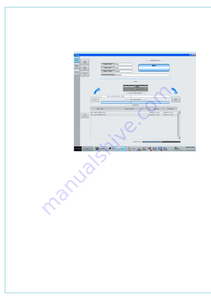
Fig 1 shows the layout of the main
application. Along the bottom edge of
the application is the main menu which
contains buttons for each of the main
sections of the application. When this
document instructs you to go to the
>Mem
section, for example, it is the
equivalent of saying: ‘touch the Mem
button in the main application main menu’.
Once a certain section has been selected,
a list of available screens will appear
vertically along the left hand edge of the
main application. Touching one of these
buttons will update the main application
to display the relevant screen. When this
document instructs you to go to a certain
screen, it is referring to touching the
relevant button on this list, down the left
hand side of the screen.
USBPort
A USB port linked to the configuration
PC is available in the reset panel located
in the upstand. This can be used for
backing up and restoring memories or
settings from the console. It is designed
for portable flash based USB memory
devices and as such may not provide
power for larger USB hard drives.
FIG 1 - MAIN APPLICATION
Installing3rdpartysoftware
Although not relied upon for console
operation, the system PC should be
considered as broadcast equipment.
Installation of software unauthorised
by Calrec may impact on the PC’s
performance and as such can invalidate
the warranty.
Powerandreset
The system PC should automatically boot
up when the control surface is powered.
If the PC screen is dark and does not
wake up when the trackball is moved,
check the AC power to the back of
the monitor and that it has not been
turned off by pressing its’ power switch.
A simple way to check if the PC is
powered is to press Caps Lock on the
keyboard and check if the Caps Lock LED
on the keyboard responds. A reset switch
for the PC is located behind the keyboard,
at the rear left-hand side. If the PC
has been shutdown but is still powered.
Pressing the reset switch should reboot it.
OnlineDocumentation
Electronic versions of all documentation
may be accessed on the configuration PC.
Summary of Contents for Artemis
Page 7: ...calrec com Putting Sound in the Picture ARTEMIS INFORMATION ...
Page 11: ...calrec com Putting Sound in the Picture ARTEMIS INTRODUCTION ...
Page 17: ...calrec com Putting Sound in the Picture ARTEMIS CONTROL OVERVIEW ...
Page 29: ...calrec com Putting Sound in the Picture ARTEMIS CONTROL PANEL MODES ...
Page 36: ...36 ARTEMIS Digital Broadcast Production Console Control Panel Modes WILDABLE CONTROLS ...
Page 39: ...calrec com Putting Sound in the Picture ARTEMIS GETTING SIGNALS INTO ARTEMIS ...
Page 69: ...calrec com Putting Sound in the Picture ARTEMIS PROCESSING AUDIO ...
Page 93: ...calrec com Putting Sound in the Picture ARTEMIS ROUTING AUDIO ...
Page 109: ...calrec com Putting Sound in the Picture ARTEMIS PASSING SIGNALS OUT OF ARTEMIS ...
Page 117: ...calrec com Putting Sound in the Picture ARTEMIS MONITORING ...
Page 132: ...132 ARTEMIS Digital Broadcast Production Console Monitoring ...
Page 133: ...calrec com Putting Sound in the Picture ARTEMIS COMMUNICATIONS ...
Page 138: ...138 ARTEMIS Digital Broadcast Production Console ...
Page 139: ...calrec com Putting Sound in the Picture ARTEMIS METERING ...
Page 148: ...148 ARTEMIS Digital Broadcast Production Console ...
Page 149: ...calrec com Putting Sound in the Picture ARTEMIS SHOWS MEMORIES AND PRESETS ...
Page 163: ...calrec com Putting Sound in the Picture ARTEMIS CONSOLE FACILITIES ...
Page 168: ...168 ARTEMIS Digital Broadcast Production Console ...
Page 169: ...calrec com Putting Sound in the Picture ARTEMIS EXTERNAL INTERFACING ...
Page 180: ...180 ARTEMIS Digital Broadcast Production Console External Interfacing ...
Page 181: ...calrec com Putting Sound in the Picture ARTEMIS SYSTEM STATUS ...
Page 184: ...184 ARTEMIS Digital Broadcast Production Console ...
Page 185: ...calrec com Putting Sound in the Picture ARTEMIS GLOSSARY OF TERMINOLOGY ...
Page 191: ...calrec com Putting Sound in the Picture ARTEMIS FEATURES BY SOFTWARE VERSION ...


