Digital Broadcast Production Console
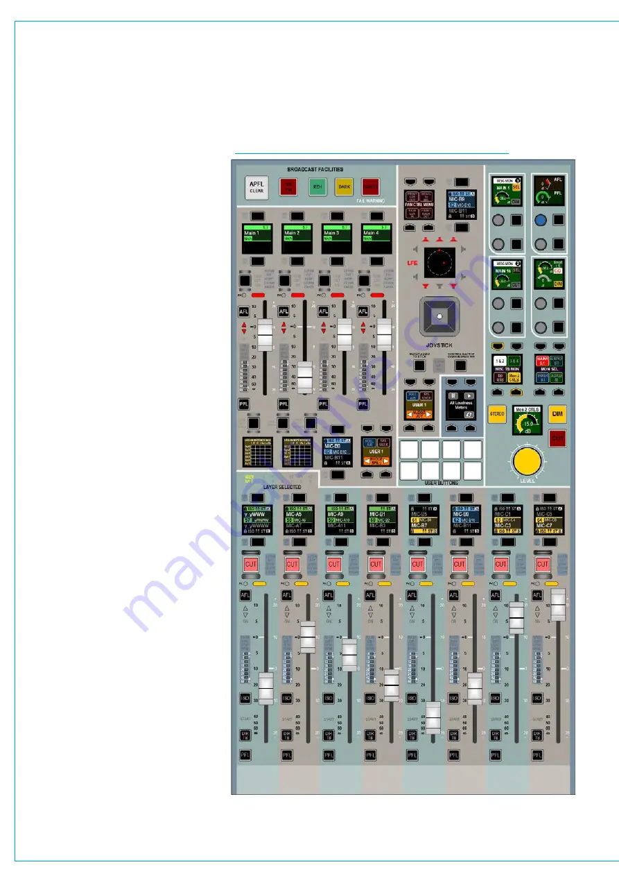
AlternateFader/MonitorPanel
There is an alternate Monitor panel that is
designed to fit in the space of a standard
fader panel which is a combination of the
bottom half of an 8 fader panel and the
monitor spill/joystick panel which is shown
on the previous page.
The fader section provides the ability to
control the 8 A/B paths assigns for Fader,
Cut, AFL, ISO, DIR TB & PFL controls.
All the other functions that are normally
available above the Assign buttons such
as the Modes and Layers Row, Function
Row and Function Control Cells, have to
be controlled from another fader panel.
This is acceptable because in assign
mode the other panels can control those
functions. The panel does show the Layer
Selected and user split status.
Above this section is a remodelled version
of the monitor panel which provides all
the controls available on that panel with
the exception of Talkback Groups which
appear on the fader panel in Talkback
mode and additional Pan controls again
which are available on the Fader panel in
Send/Route mode. This was deemed to
be an acceptable compromise given that
this panel provides the additional 8 faders
to allow a 72 fader bed on the console
without a gap and still fit in an O.B truck.
As well as monitoring controls, misc
monitoring, surround spill, surround
downmix and joystick panning. It also
provides broadcast facilities such as
On-Air/Rehearse
switching, and 8 GPIO
controls on user assignable buttons with
LED tallies.
If required, for example on a large console
or for multiple operators, multiple
fader/monitor panels can be fitted.
As well as having access to 4 miscellaneous
monitor or headphone outputs, each panel
can switch between controlling monitor 1
and monitor 2. This is achieved by the
addition of a Mon2 CRLS button in the
MISC TB MON control button cell in the
monitor section.
ARTEMIS FADER/MONITOR PANEL
Summary of Contents for Artemis
Page 7: ...calrec com Putting Sound in the Picture ARTEMIS INFORMATION ...
Page 11: ...calrec com Putting Sound in the Picture ARTEMIS INTRODUCTION ...
Page 17: ...calrec com Putting Sound in the Picture ARTEMIS CONTROL OVERVIEW ...
Page 29: ...calrec com Putting Sound in the Picture ARTEMIS CONTROL PANEL MODES ...
Page 36: ...36 ARTEMIS Digital Broadcast Production Console Control Panel Modes WILDABLE CONTROLS ...
Page 39: ...calrec com Putting Sound in the Picture ARTEMIS GETTING SIGNALS INTO ARTEMIS ...
Page 69: ...calrec com Putting Sound in the Picture ARTEMIS PROCESSING AUDIO ...
Page 93: ...calrec com Putting Sound in the Picture ARTEMIS ROUTING AUDIO ...
Page 109: ...calrec com Putting Sound in the Picture ARTEMIS PASSING SIGNALS OUT OF ARTEMIS ...
Page 117: ...calrec com Putting Sound in the Picture ARTEMIS MONITORING ...
Page 132: ...132 ARTEMIS Digital Broadcast Production Console Monitoring ...
Page 133: ...calrec com Putting Sound in the Picture ARTEMIS COMMUNICATIONS ...
Page 138: ...138 ARTEMIS Digital Broadcast Production Console ...
Page 139: ...calrec com Putting Sound in the Picture ARTEMIS METERING ...
Page 148: ...148 ARTEMIS Digital Broadcast Production Console ...
Page 149: ...calrec com Putting Sound in the Picture ARTEMIS SHOWS MEMORIES AND PRESETS ...
Page 163: ...calrec com Putting Sound in the Picture ARTEMIS CONSOLE FACILITIES ...
Page 168: ...168 ARTEMIS Digital Broadcast Production Console ...
Page 169: ...calrec com Putting Sound in the Picture ARTEMIS EXTERNAL INTERFACING ...
Page 180: ...180 ARTEMIS Digital Broadcast Production Console External Interfacing ...
Page 181: ...calrec com Putting Sound in the Picture ARTEMIS SYSTEM STATUS ...
Page 184: ...184 ARTEMIS Digital Broadcast Production Console ...
Page 185: ...calrec com Putting Sound in the Picture ARTEMIS GLOSSARY OF TERMINOLOGY ...
Page 191: ...calrec com Putting Sound in the Picture ARTEMIS FEATURES BY SOFTWARE VERSION ...


