Digital Broadcast Production Console
DOLBY E DECODING
Dolby E decoders are no longer
available as an option for fitting in
Hydra2 modular I/O boxes. However
there are a number of existing mixing
consoles that have these fitted.
If fitted, the decoders are patchable
and can be used to decode any Dolby
E signal being input to any Hydra2
I/O box on the network.
The VO5873 modular I/O card has 2 SDI
inputs and 4 slots for Dolby E decoder
modules. Multiple VO5873 cards can be
fitted within the same or different modular
I/O boxes across the network to provide
the total quantity of decoders required.
Although physically located on the same
card as SDI inputs, the Dolby E decoders
are in fact fully patchable in their own right
and can be used to decode any Dolby E
signal fed into any Hydra2 input on the
network, whether it is coming in as an
AES pair or is embedded into an SDI or
MADI stream.
LED’s A, B, C & D on the front of the
module itself illuminate green to show if
decoder cards have been fitted in the four
available slots on the module.
Passingsignalsthroughdecoders
Consoles with access to VO5873s will
display the Dolby E decoders as I/O ports
available for patching in a similar way to
regular I/O patching. Unless the I/O lists
have been customised, the decoders will
appear in the port lists labelled with the
ID number for the modular I/O boxes they
are fitted in, and like other I/O are ordered
by the slot the module is fitted in.
Dolby E encoded signals that are fed to a
Hydra2 input port and require decoding
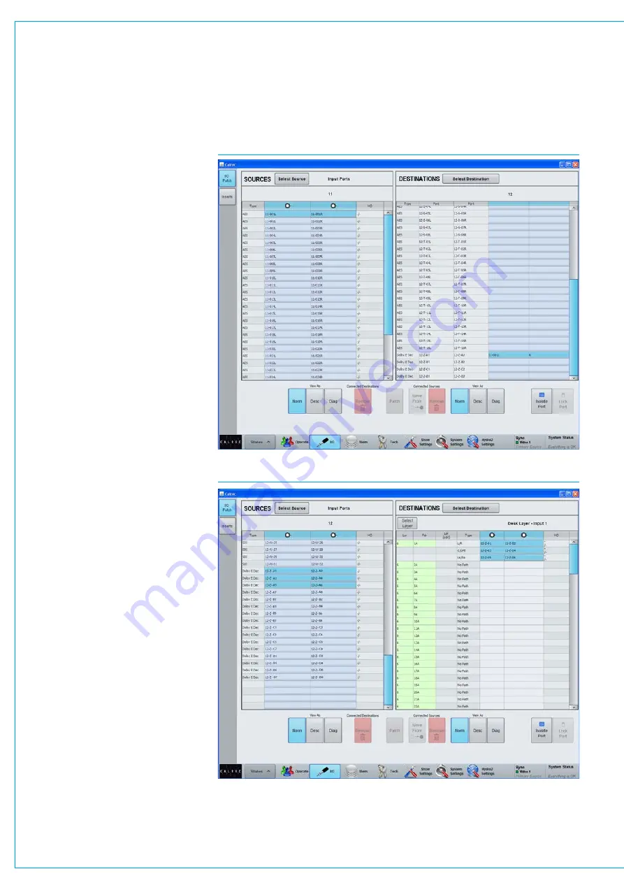
should be patched to a decoder. Using
the main application,
>I/O>I/O Patch
screen, find and highlight the input port
pair being fed with encoded signal in the
sources lists on the left side of the screen,
see Fig 1, also see
for more details
on I/O patching.
FIG 1 - AES INPUT PATCHED TO OUTPUT PORTS FEEDING A DOLBY E DECODER
FIG 2 - OUTPUT FROM A DOLBY E DECODER PATCHED TO AN INPUT CHANNEL
Summary of Contents for Artemis
Page 7: ...calrec com Putting Sound in the Picture ARTEMIS INFORMATION ...
Page 11: ...calrec com Putting Sound in the Picture ARTEMIS INTRODUCTION ...
Page 17: ...calrec com Putting Sound in the Picture ARTEMIS CONTROL OVERVIEW ...
Page 29: ...calrec com Putting Sound in the Picture ARTEMIS CONTROL PANEL MODES ...
Page 36: ...36 ARTEMIS Digital Broadcast Production Console Control Panel Modes WILDABLE CONTROLS ...
Page 39: ...calrec com Putting Sound in the Picture ARTEMIS GETTING SIGNALS INTO ARTEMIS ...
Page 69: ...calrec com Putting Sound in the Picture ARTEMIS PROCESSING AUDIO ...
Page 93: ...calrec com Putting Sound in the Picture ARTEMIS ROUTING AUDIO ...
Page 109: ...calrec com Putting Sound in the Picture ARTEMIS PASSING SIGNALS OUT OF ARTEMIS ...
Page 117: ...calrec com Putting Sound in the Picture ARTEMIS MONITORING ...
Page 132: ...132 ARTEMIS Digital Broadcast Production Console Monitoring ...
Page 133: ...calrec com Putting Sound in the Picture ARTEMIS COMMUNICATIONS ...
Page 138: ...138 ARTEMIS Digital Broadcast Production Console ...
Page 139: ...calrec com Putting Sound in the Picture ARTEMIS METERING ...
Page 148: ...148 ARTEMIS Digital Broadcast Production Console ...
Page 149: ...calrec com Putting Sound in the Picture ARTEMIS SHOWS MEMORIES AND PRESETS ...
Page 163: ...calrec com Putting Sound in the Picture ARTEMIS CONSOLE FACILITIES ...
Page 168: ...168 ARTEMIS Digital Broadcast Production Console ...
Page 169: ...calrec com Putting Sound in the Picture ARTEMIS EXTERNAL INTERFACING ...
Page 180: ...180 ARTEMIS Digital Broadcast Production Console External Interfacing ...
Page 181: ...calrec com Putting Sound in the Picture ARTEMIS SYSTEM STATUS ...
Page 184: ...184 ARTEMIS Digital Broadcast Production Console ...
Page 185: ...calrec com Putting Sound in the Picture ARTEMIS GLOSSARY OF TERMINOLOGY ...
Page 191: ...calrec com Putting Sound in the Picture ARTEMIS FEATURES BY SOFTWARE VERSION ...


