Digital Broadcast Production Console
Passing Signals Out of Artemis
OUTPUT TYPES AND PATCHING
DSP outputs including Mains, Tracks,
Auxs, Direct Outputs etc can be
patched to Hydra2 output ports,
virtual Hydra2 Patchbays, or back into
channel inputs of the same console.
Portsatdifferentsamplerates
Note that now different sample rates are
available, ports set to a different sample
rate to that of the show appear with the
SR kHz warning icon to indicate that it
cannot be used unless the sample rate of
it’s associated I/O box is changed in H2O
or a different show is loaded using the
correct sample rate. See Fig 1.
Patching
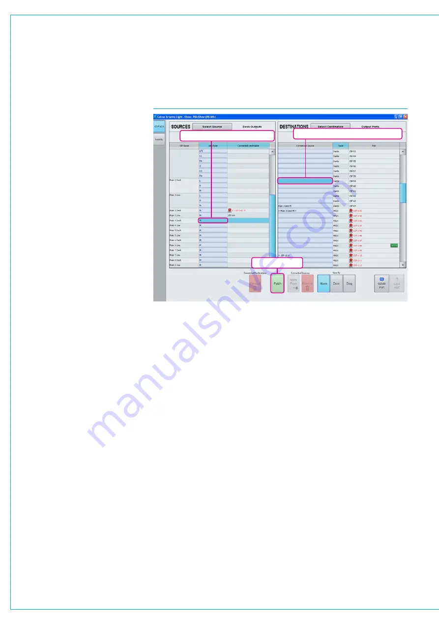
Output patching is performed in exactly
the same way as input patching, using the
I/O screens in the main application.
From the
>I/O>I/O Patch
screen (shown
in Fig 1), click the ‘Select Source’ button
at the top left of the screen and select the
appropriate output list from the ‘My Desk
Outputs’ group in the pop-up menu, the
contents of which will then be displayed in
the left hand table of the screen.
Select the required destination list on
the right hand side in the same way by
clicking the ‘Select Destination’ button.
Highlight the desired blue source cells on
the left, and the desired blue destination
cells on the right and then click ‘Patch’.
The blue cell on the right should now
display the source that has been patched
and the destination appears in the
Connected Destination column.
Patchingatdifferentsamplerates
Destinations at different sample rates to
the show including ports, hydra patchbays
and aliases can be patched (except for
System level patches) to desk inputs but
won’t work and are shown as
!! pending !!
until the sample rates are matched.
Similarly with desk outputs to Destinations
at different sample rates.
Port to port patches cannot be made for
I/O that is at a different sample rate to the
desk. However they can be made in H2O
and by SW-P-08 and will work if patched
there providing the source and destination
ports are at the same sample rate.
PatchingShortcuts
Note that the Patching Shortcuts
described earlier equally apply with output
patching as they did with input patching.
See
“Patching Shortcuts” on page 52.
Hydra2Patchbays
Virtual patch-points can be created
within the Hydra2 domain using the H2O
network administrator application.
Once configured, patch-points are
available from the I/O patching screens on
each console with access. Console DSP
outputs patched to Hydra2 Patchbays
are available for other users on the
Hydra2 network as sources without
using up physical I/O ports. In addition to
console DSP inputs and outputs, Hydra2
Patchbays can be patched to / from
physical I/O and other Hydra2 Patchbays.
This allows other users, such as a H2O
network administrator, or SW-P-08
controller to be able to select which
consoles are feeding which output ports
(e.g to select which control room is
on-air), and to be able to change sources
feeding into consoles.
HPB’satdifferentSampleRates
Any Hydra2 Patchbays that has been set
to operate at a different rate than the desk
will behave in the same way as ports at
different sample rates to the desk.
Lockingoutputportpatching
Output ports may be locked to protect
their patching from unintended
changes. To do this, the system has to
be in technician mode. The technician
selects one or more output ports in the
DESTINATIONS list and then touches the
LOCK button below right. This process is
repeated to unlock the ports again.
Locked ports are indicated by padlock
symbols on both source and destination
as shown above.
Note: Ports can only be locked and
unlocked in technician mode this facility
may be used to lock down any essential
patching and prevent user error.
For more information on technician mode,
see
.
FIG 1 - MAIN APPLICATION I/O>I/O PATCH SCREEN - I/O PATCHING
Highlight destination patch cell(s)
Patch selected
Highlight source patch cell(s)
Summary of Contents for Artemis
Page 7: ...calrec com Putting Sound in the Picture ARTEMIS INFORMATION ...
Page 11: ...calrec com Putting Sound in the Picture ARTEMIS INTRODUCTION ...
Page 17: ...calrec com Putting Sound in the Picture ARTEMIS CONTROL OVERVIEW ...
Page 29: ...calrec com Putting Sound in the Picture ARTEMIS CONTROL PANEL MODES ...
Page 36: ...36 ARTEMIS Digital Broadcast Production Console Control Panel Modes WILDABLE CONTROLS ...
Page 39: ...calrec com Putting Sound in the Picture ARTEMIS GETTING SIGNALS INTO ARTEMIS ...
Page 69: ...calrec com Putting Sound in the Picture ARTEMIS PROCESSING AUDIO ...
Page 93: ...calrec com Putting Sound in the Picture ARTEMIS ROUTING AUDIO ...
Page 109: ...calrec com Putting Sound in the Picture ARTEMIS PASSING SIGNALS OUT OF ARTEMIS ...
Page 117: ...calrec com Putting Sound in the Picture ARTEMIS MONITORING ...
Page 132: ...132 ARTEMIS Digital Broadcast Production Console Monitoring ...
Page 133: ...calrec com Putting Sound in the Picture ARTEMIS COMMUNICATIONS ...
Page 138: ...138 ARTEMIS Digital Broadcast Production Console ...
Page 139: ...calrec com Putting Sound in the Picture ARTEMIS METERING ...
Page 148: ...148 ARTEMIS Digital Broadcast Production Console ...
Page 149: ...calrec com Putting Sound in the Picture ARTEMIS SHOWS MEMORIES AND PRESETS ...
Page 163: ...calrec com Putting Sound in the Picture ARTEMIS CONSOLE FACILITIES ...
Page 168: ...168 ARTEMIS Digital Broadcast Production Console ...
Page 169: ...calrec com Putting Sound in the Picture ARTEMIS EXTERNAL INTERFACING ...
Page 180: ...180 ARTEMIS Digital Broadcast Production Console External Interfacing ...
Page 181: ...calrec com Putting Sound in the Picture ARTEMIS SYSTEM STATUS ...
Page 184: ...184 ARTEMIS Digital Broadcast Production Console ...
Page 185: ...calrec com Putting Sound in the Picture ARTEMIS GLOSSARY OF TERMINOLOGY ...
Page 191: ...calrec com Putting Sound in the Picture ARTEMIS FEATURES BY SOFTWARE VERSION ...


