CancelAFLandPFL
When any AFL or PFL is active, the APFL
indicator on the Broadcast Facilities panel
illuminates. Press this button to cancel all
AFL and PFLs that are currently active.
See Fig 3 on the previous page.
There is also an APFL cancel button on
the TFT screen when in Monitor mode.
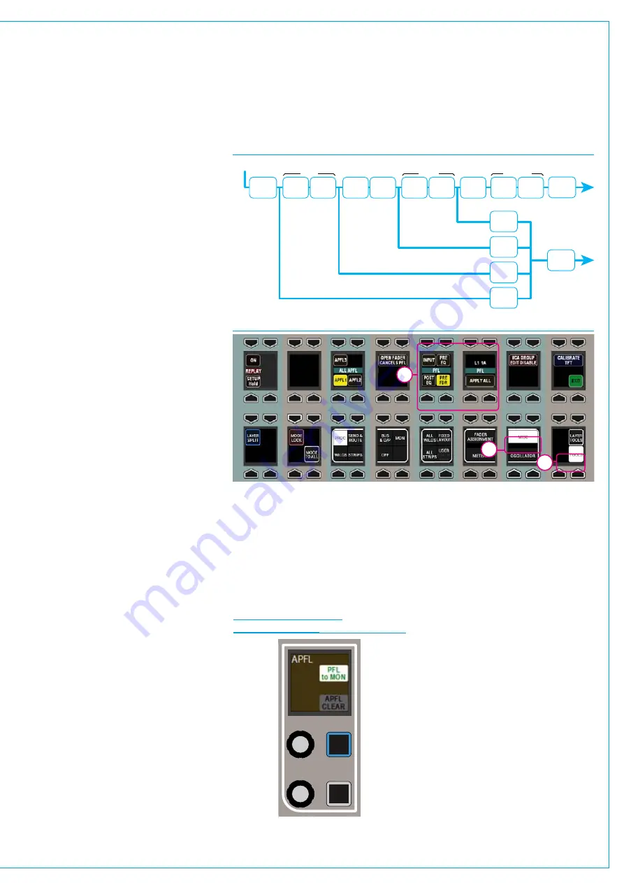
MovePFLwithinsignalchain
PFL can be selected to output from
various points within a path’s signal
flow, see Fig 4 above right. Select
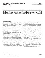
TOOLS>MISC from any fader panel’s
button cell row to show APFL options in
the row above, see Fig 5. A short press of
one of the selection buttons changes the
PFL point for the current assign path. To
change multiple paths, press and hold the
desired selection button whilst selecting
paths by pressing their fader assign
buttons. To change all paths on the
surface, or within the user split, press and
hold APPLY TO ALL/APPLY TO USER
SECTION button then press the required
PFL selection point. When a path fader
PFL is activated, the fader label display
momentarily displays the PFLs selected
location.
PatchAFL/PFLtoexternalmonitors
Navigate to
>System Settings>Fixed I/O
screen in the section of the main
application. Push the ‘Select Source’
button and select ‘Monitor Outputs’ from
the popup that appears. The source list
will now make all monitor outputs of the
system available for patching, including
the three independent AFL and PFL
systems for each user section. Simply
select the required source and destination
ports and push the ‘Patch’ button.
SendPFLtothesmallLS
The system can be configured to route
PFL signals to the small loudspeaker,
overriding any other signal presently going
to it.
This is a factory defined configuration and
should be specified when the console is
ordered.
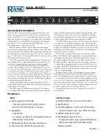
FIG 6 - MONITOR PANEL
MODE PFL TO MON
INPUT
INSERT
DYNAMICS
EQ
WIDTH
INSERT DYNAMICS
FADER
INSERT DYNAMICS
POST SEND
/ ROUTING
SIGNAL IN
PRE EQ
POST EQ
POST FADER
POST EQ
PFL SEL
PRE FADER
PFL SEL
PRE EQ
PFL SEL
INPUT
PFL SEL
PFL
OUTPUT
FIG 4 - PFL OPTIONS WITHIN PATH SIGNAL FLOW
FIG 5 - SELECTING PFL POINT WITHIN PATH
1
2
3
SendPFLtothemainmonitors
To send the PFL signal to the main
monitors rather than the dedicated
PFL/RTB output, press the PFL to MON
button found in the Monitor panel mode.
See Fig 6 below.
AFLandPFLwithmultipleusers
When working with multiple user splits
in the surface, each user can use an
individual APFL bus. The choice of which
bus to using controls in the functions row.
Push TOOLS then MISC on the layers
row and the available options for APFL
system selection appear on the updated
Functions row above. Press one of these
buttons in each user area to set the active
APFL system for that area as shown
above. Repeat this process in each user
split. See Fig 7 on the next page.
APFL systems can be selected to be
routed to ‘Monitor 1’ and ‘Monitor 2’:
To do this set an assignable panel into
Monitor mode and select any of the four
monitor pre-selectors to ensure that the
source selection screen on the TFT is
referring to the main monitor rather than a
miscellaneous monitor or meter selector.
Summary of Contents for Artemis
Page 7: ...calrec com Putting Sound in the Picture ARTEMIS INFORMATION ...
Page 11: ...calrec com Putting Sound in the Picture ARTEMIS INTRODUCTION ...
Page 17: ...calrec com Putting Sound in the Picture ARTEMIS CONTROL OVERVIEW ...
Page 29: ...calrec com Putting Sound in the Picture ARTEMIS CONTROL PANEL MODES ...
Page 36: ...36 ARTEMIS Digital Broadcast Production Console Control Panel Modes WILDABLE CONTROLS ...
Page 39: ...calrec com Putting Sound in the Picture ARTEMIS GETTING SIGNALS INTO ARTEMIS ...
Page 69: ...calrec com Putting Sound in the Picture ARTEMIS PROCESSING AUDIO ...
Page 93: ...calrec com Putting Sound in the Picture ARTEMIS ROUTING AUDIO ...
Page 109: ...calrec com Putting Sound in the Picture ARTEMIS PASSING SIGNALS OUT OF ARTEMIS ...
Page 117: ...calrec com Putting Sound in the Picture ARTEMIS MONITORING ...
Page 132: ...132 ARTEMIS Digital Broadcast Production Console Monitoring ...
Page 133: ...calrec com Putting Sound in the Picture ARTEMIS COMMUNICATIONS ...
Page 138: ...138 ARTEMIS Digital Broadcast Production Console ...
Page 139: ...calrec com Putting Sound in the Picture ARTEMIS METERING ...
Page 148: ...148 ARTEMIS Digital Broadcast Production Console ...
Page 149: ...calrec com Putting Sound in the Picture ARTEMIS SHOWS MEMORIES AND PRESETS ...
Page 163: ...calrec com Putting Sound in the Picture ARTEMIS CONSOLE FACILITIES ...
Page 168: ...168 ARTEMIS Digital Broadcast Production Console ...
Page 169: ...calrec com Putting Sound in the Picture ARTEMIS EXTERNAL INTERFACING ...
Page 180: ...180 ARTEMIS Digital Broadcast Production Console External Interfacing ...
Page 181: ...calrec com Putting Sound in the Picture ARTEMIS SYSTEM STATUS ...
Page 184: ...184 ARTEMIS Digital Broadcast Production Console ...
Page 185: ...calrec com Putting Sound in the Picture ARTEMIS GLOSSARY OF TERMINOLOGY ...
Page 191: ...calrec com Putting Sound in the Picture ARTEMIS FEATURES BY SOFTWARE VERSION ...


