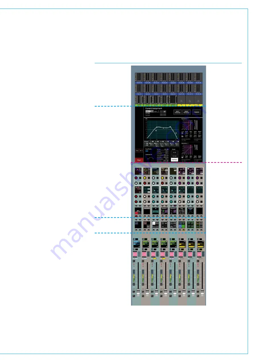
A typical Artemis control surface is
made up of a number of identical
surface panels in the control bed
to make up the required quantity of
physical faders.
Fader&TFTPanels
For each standard control bed fader panel
fitted, a TFT panel is usually fitted in the
upstand above. See Fig 1.
The functionality of the standard control
bed panel is split - the lower section
comprises of the faders and associated
path controls. The upper section works in
conjunction with the upstand panel above
if fitted, giving access to various modes
of control functionality. In between these
two areas is the Modes Row which is used
to config the areas above and below.
The upper section of the upstand TFT
panel is used for displaying audio meters.
Fader panels can be fitted without an
associated upstand TFT panel if required,
however such panels would not provide
access to some of the selectable panel
mode functions.
A control surface with only one full fader
panel and upstand TFT panel pair fitted
gives full access to all control parameters
by switching between panel modes,
however multiple panels are normally
fitted to reduce the amount of mode
switching required, as well as to make all
controls close to hand from any physical
position along the width of the control
surface.
The ability to put any panel pair into
any mode also provides redundancy in
the event of a panel being damaged.
Maximizing the number of upstand panels
fitted also maximises the audio metering
available across the upstand.
FIG 1 - FADER CONTROL PANEL AND UPSTAND TFT PANEL COMBINATION
SURFACE PANEL OVERVIEW
Upstand
Control bed
Configurable
metering
Selectable Panel
mode area
Modes and Layers
row
Functions row
Path controls
Summary of Contents for Artemis
Page 7: ...calrec com Putting Sound in the Picture ARTEMIS INFORMATION ...
Page 11: ...calrec com Putting Sound in the Picture ARTEMIS INTRODUCTION ...
Page 17: ...calrec com Putting Sound in the Picture ARTEMIS CONTROL OVERVIEW ...
Page 29: ...calrec com Putting Sound in the Picture ARTEMIS CONTROL PANEL MODES ...
Page 36: ...36 ARTEMIS Digital Broadcast Production Console Control Panel Modes WILDABLE CONTROLS ...
Page 39: ...calrec com Putting Sound in the Picture ARTEMIS GETTING SIGNALS INTO ARTEMIS ...
Page 69: ...calrec com Putting Sound in the Picture ARTEMIS PROCESSING AUDIO ...
Page 93: ...calrec com Putting Sound in the Picture ARTEMIS ROUTING AUDIO ...
Page 109: ...calrec com Putting Sound in the Picture ARTEMIS PASSING SIGNALS OUT OF ARTEMIS ...
Page 117: ...calrec com Putting Sound in the Picture ARTEMIS MONITORING ...
Page 132: ...132 ARTEMIS Digital Broadcast Production Console Monitoring ...
Page 133: ...calrec com Putting Sound in the Picture ARTEMIS COMMUNICATIONS ...
Page 138: ...138 ARTEMIS Digital Broadcast Production Console ...
Page 139: ...calrec com Putting Sound in the Picture ARTEMIS METERING ...
Page 148: ...148 ARTEMIS Digital Broadcast Production Console ...
Page 149: ...calrec com Putting Sound in the Picture ARTEMIS SHOWS MEMORIES AND PRESETS ...
Page 163: ...calrec com Putting Sound in the Picture ARTEMIS CONSOLE FACILITIES ...
Page 168: ...168 ARTEMIS Digital Broadcast Production Console ...
Page 169: ...calrec com Putting Sound in the Picture ARTEMIS EXTERNAL INTERFACING ...
Page 180: ...180 ARTEMIS Digital Broadcast Production Console External Interfacing ...
Page 181: ...calrec com Putting Sound in the Picture ARTEMIS SYSTEM STATUS ...
Page 184: ...184 ARTEMIS Digital Broadcast Production Console ...
Page 185: ...calrec com Putting Sound in the Picture ARTEMIS GLOSSARY OF TERMINOLOGY ...
Page 191: ...calrec com Putting Sound in the Picture ARTEMIS FEATURES BY SOFTWARE VERSION ...


