Digital Broadcast Production Console
ASSIGNING PATHS
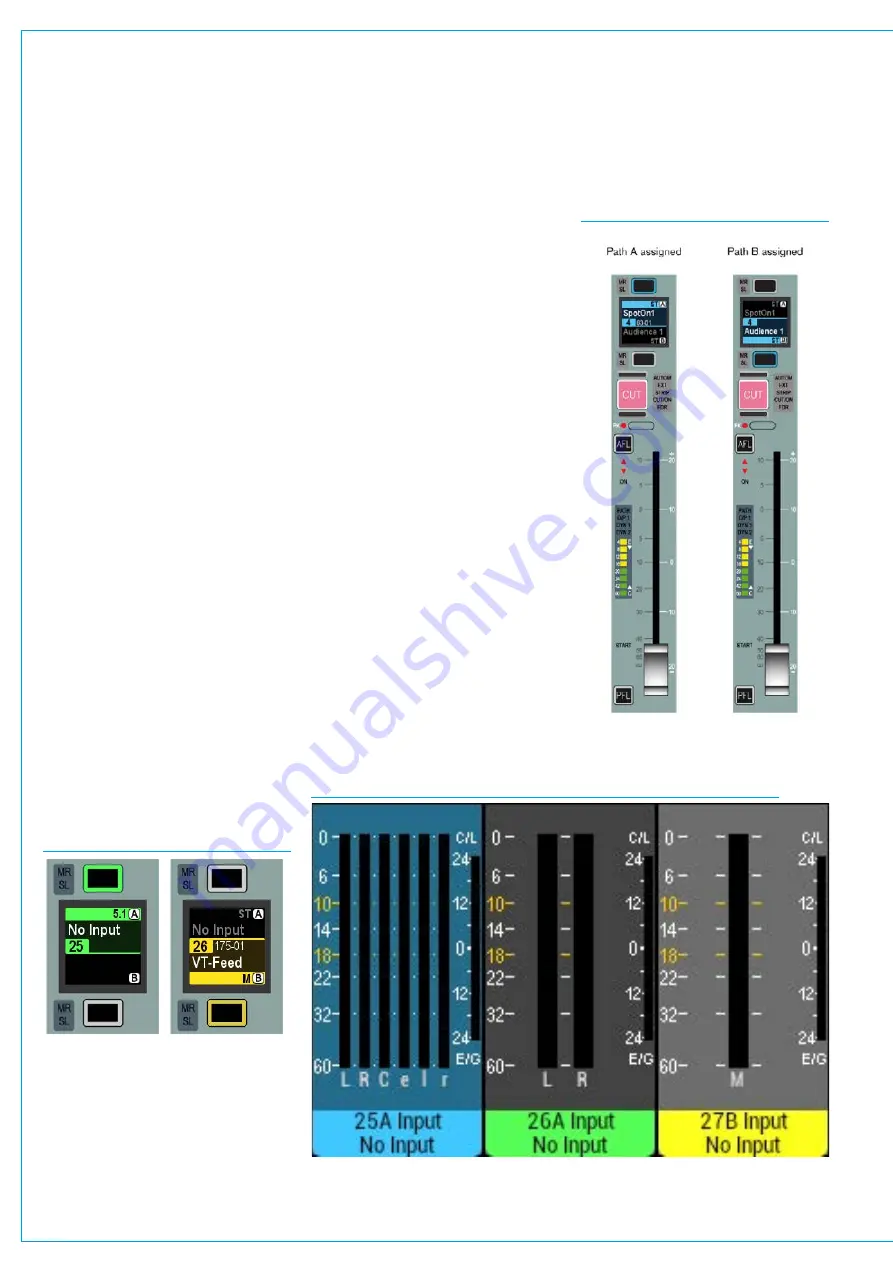
CurrentAssignandFaderTouch
IndicationshownonMeters
When an assign button is pressed the
associated meter highlights in a matching
colour to the blue assign button and blue
background for the fader display. This is
to further clarify which is the currently
assigned path, see Fig 3. Fader 25A
below left.
In addition when fader knobs are touched
the background of the associated upstand
meter highlights to indicate those paths,
see Fig 3. Fader 27B below right.
An important concept of Calrec
consoles is that of assignability.
This allows controls to be shared
amongst all paths, reducing physical
space requirements and providing
quick and familiar access.
When a path is assigned, certain areas of
the surface will display and allow control
of parameters of that assigned path.
For example, any wild assign panels
in Assign mode and the surround spill
panel will update to reflect values of the
currently assigned path. Assigning a
different path will alter these displayed
values.
Assigningapath
Above each fader is a display and two
buttons as shown in Fig. 1 below. The
display shows the name of the A and B
paths of each fader.
The upper section (green) shows the A
path and the lower section (yellow) shows
the B path.
The path that is currently being
controlled by the fader takes up a greater
percentage of the display area, is coloured
with the relevant colour and has the
relevant assign button lit.
FIG 1 - ASSIGN BUTTONS
FIG 2 - A/B PATH ASSIGNMENTS
FIG 3 - CURRENT ASSIGNMENT AND FADER TOUCH SHOWN ON METERS
To assign either of these paths, press the
relevant button above or below the display
(above for path A, below for path B).
The section of the display showing the
assigned path will turn blue to indicate the
current assignment. The relevant button
will also light up blue as confirmation.
The fader will now control the assigned
path as shown in Fig 2 (shown right).
Other areas of the surface that are set up
to respond to Assignments will display and
control parameters of this selected path.
Summary of Contents for Artemis
Page 7: ...calrec com Putting Sound in the Picture ARTEMIS INFORMATION ...
Page 11: ...calrec com Putting Sound in the Picture ARTEMIS INTRODUCTION ...
Page 17: ...calrec com Putting Sound in the Picture ARTEMIS CONTROL OVERVIEW ...
Page 29: ...calrec com Putting Sound in the Picture ARTEMIS CONTROL PANEL MODES ...
Page 36: ...36 ARTEMIS Digital Broadcast Production Console Control Panel Modes WILDABLE CONTROLS ...
Page 39: ...calrec com Putting Sound in the Picture ARTEMIS GETTING SIGNALS INTO ARTEMIS ...
Page 69: ...calrec com Putting Sound in the Picture ARTEMIS PROCESSING AUDIO ...
Page 93: ...calrec com Putting Sound in the Picture ARTEMIS ROUTING AUDIO ...
Page 109: ...calrec com Putting Sound in the Picture ARTEMIS PASSING SIGNALS OUT OF ARTEMIS ...
Page 117: ...calrec com Putting Sound in the Picture ARTEMIS MONITORING ...
Page 132: ...132 ARTEMIS Digital Broadcast Production Console Monitoring ...
Page 133: ...calrec com Putting Sound in the Picture ARTEMIS COMMUNICATIONS ...
Page 138: ...138 ARTEMIS Digital Broadcast Production Console ...
Page 139: ...calrec com Putting Sound in the Picture ARTEMIS METERING ...
Page 148: ...148 ARTEMIS Digital Broadcast Production Console ...
Page 149: ...calrec com Putting Sound in the Picture ARTEMIS SHOWS MEMORIES AND PRESETS ...
Page 163: ...calrec com Putting Sound in the Picture ARTEMIS CONSOLE FACILITIES ...
Page 168: ...168 ARTEMIS Digital Broadcast Production Console ...
Page 169: ...calrec com Putting Sound in the Picture ARTEMIS EXTERNAL INTERFACING ...
Page 180: ...180 ARTEMIS Digital Broadcast Production Console External Interfacing ...
Page 181: ...calrec com Putting Sound in the Picture ARTEMIS SYSTEM STATUS ...
Page 184: ...184 ARTEMIS Digital Broadcast Production Console ...
Page 185: ...calrec com Putting Sound in the Picture ARTEMIS GLOSSARY OF TERMINOLOGY ...
Page 191: ...calrec com Putting Sound in the Picture ARTEMIS FEATURES BY SOFTWARE VERSION ...


