JOYSTICK PANNING
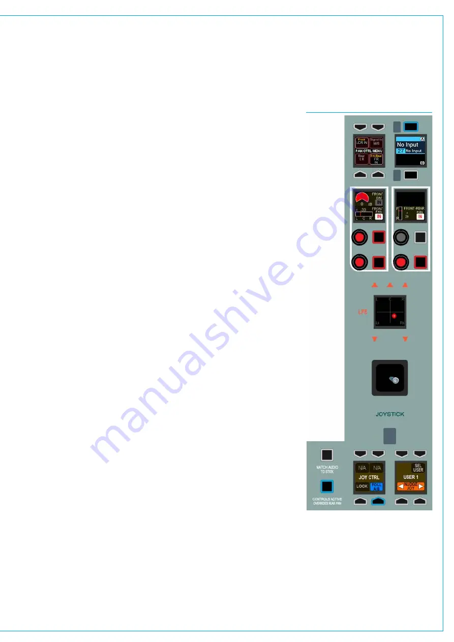
FIG 1 - JOYSTICK CONTROLS
Two dedicated monitor panel types
are available for the Artemis control
surface, one of these includes
controls for surround spill and
surround downmix faders as well as a
joystick for panning.
Please note that the alternate version of
dedicated monitor panel does not provide
joystick or spill / downmix controls. The
illustration on the right shows the joystick
controls that are available if the full-
featured dedicated monitor panel is fitted.
Accessingthejoystickcontrols
The information displayed on the joystick
controls relates to the path shown in
the upper left button cell display. This
display and its assign buttons function in
the same way as the fader label displays
above each fader. This path can be
selected in a number of ways.
Fig 1 shows which path the joystick is
controlling. If FOLL A/B is selected from
the JOY CTRL cell at the bottom left, the
joystick controls follow whichever is the
currently assigned path on the surface (or
within the selected user split).
Selecting LOCK prevents the joystick’s
focus from changing, locking the controls
to the path that was the focus at the time
the lock button is pressed.
The adjacent control cell allows the focus
of the joystick controls to be changed
without pressing path assign buttons by
using the ‘NUDGE’ left and right buttons
to move the focus to the next path on the
surface.
If the console is set up for multiple
operators with user splits, the same
control cell also allows the user split
area that the joysticks can control to be
selected by pressing SEL USER.
All other controls in the area shown,
including the rotary pan controls and the
joystick itself are inactive and cannot
affect the currently selected path unless
CONTROLS ACTIVE is selected from the
bottom left.
Makingthejoystickcontrolsactive
When the required path has been
assigned, the joystick controls must
be made active. To do this, press the
CONTROLS ACTIVE button. The controls
can now be used to alter the pan position.
The two control cells above the joystick
contain rotary controls and In buttons
for the front L-R pan, the Front-Rear pan
and the L-C-R divergence control. These
mirror and affect the same parameters
as pan controls found on the Send-Route
panel mode and that can be placed on
path wild control cells - changing these
parameters from any location will update
the displays on all accordingly.-
The joystick itself provides a single control
that can adjust the L-R and front-rear
pans. Movement of the joystick changes
the individual pan settings and their
displays will reflect this. As the joystick is
in fact controlling the same parameters as
the individual pans, the pans themselves
need to be switched in for the joystick to
have an effect on their axes.
Pandisplay
The display above the joystick is
surrounded by loudspeaker symbols which
illuminate to indicate the output width of
the path. The centre channel speaker
symbol illuminates when the centre
channel is enabled by switching the front
pan to L-C-R. The rear speaker symbols
illuminate when the path’s rear output
channels are enabled by switching in the
front-rear pan. Although LFE level cannot
be controlled by the joystick, indication
illuminates to show when the LFE channel
of a path is active.
Summary of Contents for Artemis
Page 7: ...calrec com Putting Sound in the Picture ARTEMIS INFORMATION ...
Page 11: ...calrec com Putting Sound in the Picture ARTEMIS INTRODUCTION ...
Page 17: ...calrec com Putting Sound in the Picture ARTEMIS CONTROL OVERVIEW ...
Page 29: ...calrec com Putting Sound in the Picture ARTEMIS CONTROL PANEL MODES ...
Page 36: ...36 ARTEMIS Digital Broadcast Production Console Control Panel Modes WILDABLE CONTROLS ...
Page 39: ...calrec com Putting Sound in the Picture ARTEMIS GETTING SIGNALS INTO ARTEMIS ...
Page 69: ...calrec com Putting Sound in the Picture ARTEMIS PROCESSING AUDIO ...
Page 93: ...calrec com Putting Sound in the Picture ARTEMIS ROUTING AUDIO ...
Page 109: ...calrec com Putting Sound in the Picture ARTEMIS PASSING SIGNALS OUT OF ARTEMIS ...
Page 117: ...calrec com Putting Sound in the Picture ARTEMIS MONITORING ...
Page 132: ...132 ARTEMIS Digital Broadcast Production Console Monitoring ...
Page 133: ...calrec com Putting Sound in the Picture ARTEMIS COMMUNICATIONS ...
Page 138: ...138 ARTEMIS Digital Broadcast Production Console ...
Page 139: ...calrec com Putting Sound in the Picture ARTEMIS METERING ...
Page 148: ...148 ARTEMIS Digital Broadcast Production Console ...
Page 149: ...calrec com Putting Sound in the Picture ARTEMIS SHOWS MEMORIES AND PRESETS ...
Page 163: ...calrec com Putting Sound in the Picture ARTEMIS CONSOLE FACILITIES ...
Page 168: ...168 ARTEMIS Digital Broadcast Production Console ...
Page 169: ...calrec com Putting Sound in the Picture ARTEMIS EXTERNAL INTERFACING ...
Page 180: ...180 ARTEMIS Digital Broadcast Production Console External Interfacing ...
Page 181: ...calrec com Putting Sound in the Picture ARTEMIS SYSTEM STATUS ...
Page 184: ...184 ARTEMIS Digital Broadcast Production Console ...
Page 185: ...calrec com Putting Sound in the Picture ARTEMIS GLOSSARY OF TERMINOLOGY ...
Page 191: ...calrec com Putting Sound in the Picture ARTEMIS FEATURES BY SOFTWARE VERSION ...


