3 Omega
with Bluefin
D
2
5
F
-S
P
J34
R
E
L
A
Y
C
O
M
M
O
N
D
3
7
F
-S
P
R
E
L
A
Y
N
O
&
N
M
J35
D
3
7
M
-S
P
P
S
U
&
F
A
N
M
O
N
IT
O
R
IN
G
R
E
L
A
Y
F
IR
IN
G
L
IN
E
S
H
P
&
T
B
A
U
D
IO
R
A
C
K
R
E
S
E
T
J33
9
F
D
-T
Y
P
E
J26
H
P
&
T
B
A
U
D
IO
P
O
W
E
R
8
D
V
-S
T
O
C
O
N
S
O
L
E
2
4
V
D
C
O
U
T
P
U
T
2
J6
P
O
W
E
R
8
D
V
-S
T
O
C
O
N
S
O
L
E
2
4
V
D
C
O
U
T
P
U
T
1
J2
9
M
D
-T
Y
P
E
J19
D
IG
IO
R
A
C
K
R
E
S
E
T
O
U
T
P
U
T
&
F
A
N
F
A
IL
I
N
P
U
T
9
M
D
-T
Y
P
E
J32
D
S
P
R
A
C
K
R
E
S
E
T
O
U
T
P
U
T
&
F
A
N
F
A
IL
I
N
P
U
T
P
O
W
E
R
5
D
V
-S
J8
2
4
V
D
C
O
U
T
P
U
T
#
2
J9
A
U
X
IL
IA
R
Y
2
4
V
O
/P
#
2
P
O
W
E
R
5
D
V
-S
J7
2
4
V
D
C
O
U
T
P
U
T
#
1
J3
A
U
X
IL
IA
R
Y
2
4
V
O
/P
#
1
P
O
W
E
R
5
D
V
-S
J11
2
4
V
D
C
O
U
T
P
U
T
#
4
P
O
W
E
R
5
D
V
-S
J10
2
4
V
D
C
O
U
T
P
U
T
#
3
9
F
D
-T
Y
P
E
J22
A
N
A
L
O
G
R
A
C
K
#
3
R
E
S
E
T
O
/P
F
A
N
F
A
IL
I/
P
&
F
A
N
2
4
V
9
M
D
-T
Y
P
E
J18
A
N
A
L
O
G
P
S
U
#
3
M
O
N
&
R
A
C
K
F
A
N
2
4
V
9
F
D
-T
Y
P
E
J21
A
N
A
L
O
G
R
A
C
K
#
2
R
E
S
E
T
O
/P
F
A
N
F
A
IL
I/
P
&
F
A
N
2
4
V
P
O
W
E
R
8
D
V
-P
F
R
O
M
A
N
A
L
O
G
P
S
U
J15
P
O
W
E
R
8
D
V
-S
T
O
A
N
A
L
O
G
R
A
C
K
S
J16
P
O
W
E
R
8
D
V
-S
F
R
O
M
A
N
A
L
O
G
P
S
U
J12
P
O
W
E
R
8
D
V
-P
T
O
A
N
A
L
O
G
R
A
C
K
S
J13
P
O
W
E
R
8
D
V
-P
F
R
O
M
A
N
A
L
O
G
P
S
U
J14
9
M
D
-T
Y
P
E
J17
A
N
A
L
O
G
P
S
U
#
2
M
O
N
&
R
A
C
K
F
A
N
2
4
V
9
F
D
-T
Y
P
E
J20
A
N
A
L
O
G
R
A
C
K
#
1
R
E
S
E
T
O
/P
F
A
N
F
A
IL
I/
P
&
F
A
N
2
4
V
9
M
D
-T
Y
P
E
J31
A
N
A
L
O
G
P
S
U
#
1
M
O
N
&
R
A
C
K
F
A
N
2
4
V
ZH5527 PSU RACK
P
O
W
E
R
3
D
V
-S
P
O
W
E
R
3
D
V
-S
POWER
AC
POWER
AC
POWER
AC
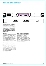
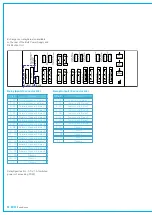
Power Supply, Monitoring and Distribution Unit (Rear)
Console Interface
HN5637 CONSOLE INTERFACE
J44
GPI #2
50F D-TYPE
50F D-TYPE
50F D-TYPE
50F D-TYPE
J46
J32
J45
GPI #1
GPI #3
GPI #4
1
1
1
1
1
D37F-SP-PF
J58
PSU MON/RESET
J12
RJ45-8V
METER DATA
J11
RJ45-8V
FAST LINK
J1
RJ45-8V
RS422#2
J3
RJ45-8V
DEBUG#2
J39
RJ45-8V
RS422#1
J2
RJ45-8V
DEBUG#1
9M D-TYPE
1
J41
RS232
9M D-TYPE
1
J40
RS232
9M D-TYPE
1
J49
RS232
P
O
W
E
R
8
D
V
J43
1
P
O
W
E
R
8
D
V
J42
1
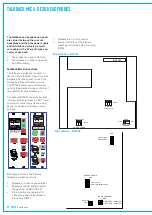
Microphone audio
The output of the microphone amplifier
is available in analog or digital form
depending on the setting of the DIL
switch inside the reset panel (SW5). It
can be wired to a comms system or to
a console input port as required. Whilst
connections can be made by adding a
cable to the already cabled 37 way D type
connector, J58 on the rear of the console
surface, it is normally preferable and a
simpler wiring task to use the 9 pin one
on the rear of the PSU monitoring and
distribution unit that is near equipment
racks.
Headphone audio
As with the microphone, either the rear
of the console or the PSU monitoring
and distribution unit can be used to
connect headphone signals. Once again,
it is preferable to wire to the dedicated
9 pin connector on the rear of the
PSU monitoring and distribution unit.
Remember that headphone feeds can
only be AES signals.
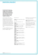
Connector J26 Pin Out Information
On the rear of the PSU monitoring and
distribution unit, connector J26:-
Pins 1 and 2 - From control surface TB
mic (AES or analog)
Pins 4 and 5 - To control surface
headphone jack (AES only).
Headphone and talkback mic
Connections for desk headphone and
talkback mic signals are made to 9 pin
D-type connector on the rear of the PSU
monitoring and distribution unit. This is a
female panel mount connector, requiring a
male on the cables.
Remember that headphone feeds can
only be AES digital signals.
Summary of Contents for OMEGA
Page 7: ...calrec com OMEGA Putting Sound in the Picture Overview...
Page 13: ...calrec com OMEGA Putting Sound in the Picture Frame Options and Dimensions...
Page 18: ...18 OMEGA with Bluefin...
Page 19: ...calrec com OMEGA Putting Sound in the Picture Equipment Installation...
Page 37: ...calrec com OMEGA Putting Sound in the Picture Hydra Audio Networking...
Page 51: ...calrec com OMEGA Putting Sound in the Picture Audio I O Interfaces...


