All rights reserved. No spreading abroad without permission of Caltta.
PM790 Radio Maintenance Manual
34
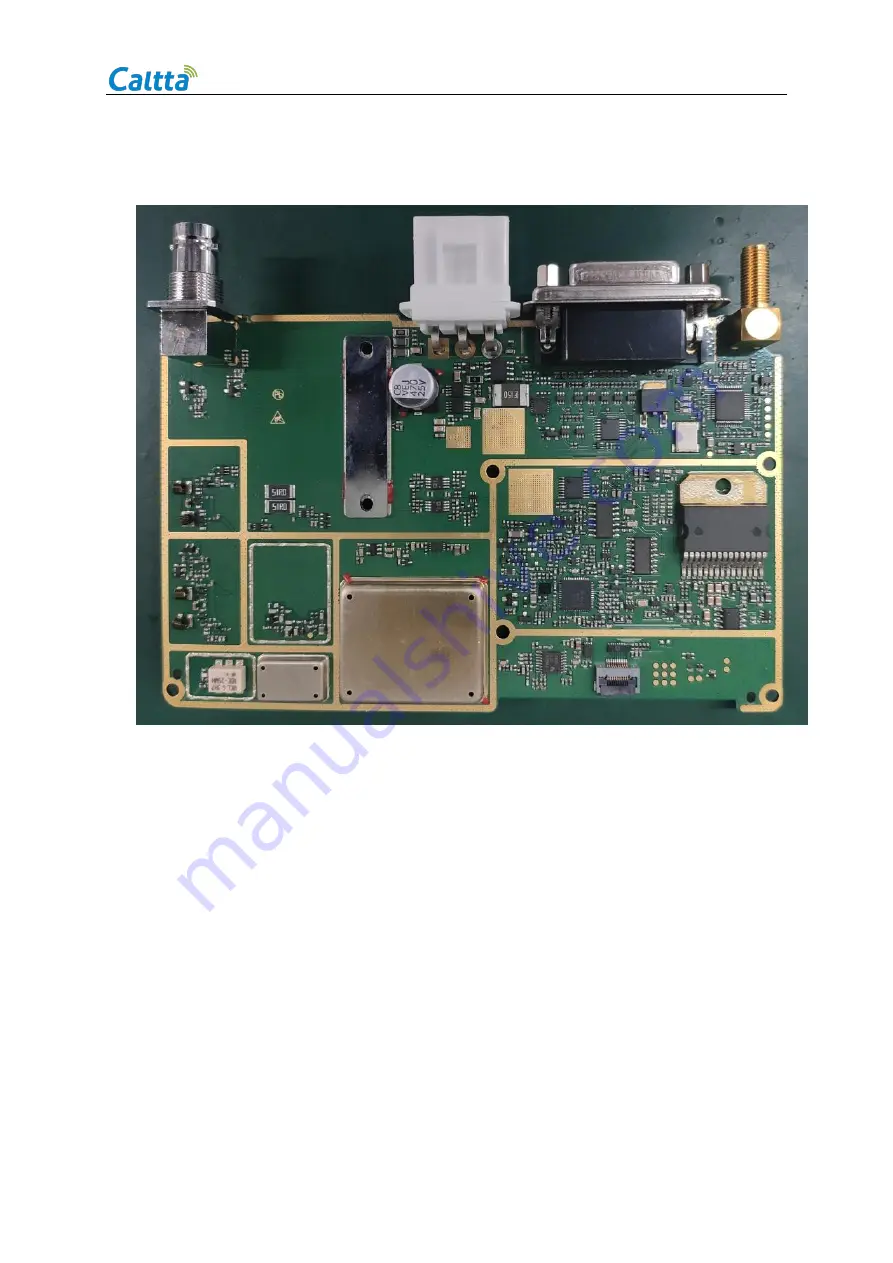
5.2Back of Main PCB
6 Troubleshooting Maintenance Flow
6.1Structural Part Failure
For the failure of radio structural parts, please refer to 4.2 Disassemble Steps for replacement.
6.2Baseband Circuits Troubleshooting Overview
After the radio is powered on, the radio starts normally and the current is about 330mA. During the
startup process, the LED indicator flashes green and the LCD displays normally. When the LCD
Summary of Contents for PM790
Page 1: ...1 PM790 Radio MAINTENANCE MANUAL Level1 V1 0...
Page 2: ......


