background image

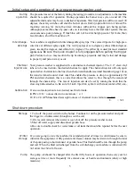
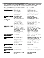
Troubleshooting: common problems and solutions

Cause

-Switch in ‘off’ position
-Machine not plugged in
-GFCI tripped
-Overload on motor tripped

-Circuit breaker tripped

-Water supply not turned on
-Plugged nozzle on wand
-Trigger gun off or malfunctioning

-Plugged spray nozzle
-Inlet screen is plugged
-Insufficient water supply
-Unloader valve stuck open
-Plugged inlet or discharge hose
-Use of additional lengths of hose

-Partially plugged spray nozzle
-Worn nozzle
-Soap (low pressure tip installed)
-Restricted or leaking water hose
-Cavitation (inadequate water supply)
-Worn pump packings
-Fouled inlet or discharge valves
-Broken valve spring
-Worn or restricted unloader valve

-Restricted discharge

-Valve on gun/wand not open

-Injector valve not turned on
-Discharge hose too long

-Clogged injector pick-up hose
-Clogged injector

-Worn plungers or packings

-All valves fouled
-Unloader valve seat fouled

-Leak in trigger or discharge

-High humidity or direct water spray
-Worn seals

Malfunction

PPrreessssuurree w

waasshheerr w

wiillll nnoott rruunn

U

Unniitt  rruunnss  bbuutt  nnoo  w

waatteerr  ddiiss-

cchhaarrggeess

LLoow

w nnoozzzzllee pprreessssuurree

SSuurrggiinngg  pprreessssuurree  oorr  ddrroopp  iinn
pprreessssuurree

PPrreessssuurree aatt ppuum

mpp bbuutt lloow

w ddiiss-

cchhaarrggee pprreessssuurree aatt gguunn

C

Chheem

miiccaall iinnjjeeccttoorr nnoott w

woorrkkiinngg

pprrooppeerrllyy

W

Waatteerr lleeaakkss ffrroom

m ppuum

mpp m

maannii-

ffoolldd

U

Unnllooaaddeerr ddooeess nnoott bbyyppaassss

U

Unnllooaaddeerr  ccyycclleess  w

whheenn  gguunn  iiss

sshhuutt ooffff

W

Waatteerr iinn ccrraannkkccaassee

Remedy

-Turn switch to ‘on’ position
-Plug machine into adequate service
-Reset GFCI
-Allow automatic overload to cool or push the

reset button located on motor to reset

-Reset circuit breaker in main panel

-Turn on water supply
-Remove, clean, or replace nozzle
-Remove, repair, or replace trigger gun

-Remove nozzle and clean or replace
-Remove filter and clean or replace
-Secure adequate water supply
-Disassemble and clean; repair or replace
-Flush or replace hoses
-Reduce discharge hose length.

-Remove nozzle and clean or replace
-Remove and replace nozzle
-Remove and install one of the nozzles
-Check inlet hose and filter; clean or replace
-Secure adequate water supply
-Inspect and replace worn packings
-Inspect valves and clean or replace
-Inspect and replace valve spring
-Inspect unloader and repair or replace

-Check for discharge obstructions in injector,

hose, wand, and unloader

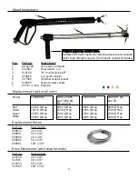
-Open valve by turning forward handle counter-

clockwise. (see wand breakdown page 10)

-Turn on injector by turning fitting on injector
-Reduce hose length or reposition injector to

within forty feet of trigger gun

-Remove and clean or replace
-Disassemble, clean, and reassemble

-Inspect and replace

-Inspect valves and clean or replace
-Inspect and clean or replace

-Inspect leaking fittings and repair or replace

-Reduce oil change intervals
-Replace seals

Despite the complexity of your power washing equipment, a number of common complaints stem from rela-
tively simple problems. With guidance, the user can identify and remedy many common problems.

Always disconnect the power supply before attempting to service any equipment.

6

Summary of Contents for 1450SHDE

Page 1: ...ec 2 0 Elec 3 0 Elec 3 0 Elec 5 0 elec 5 0 Elec 5 0 Elec 7 5 Elec 7 5 Elec 5 0 Elec 7 5 Elec 10 0 Elec F Fu ue el l t ty yp pe e For all No 1 diesel No 2 diesel or kerosene W We ei ig gh ht t l lb bs s 350 350 350 350 350 360 570 525 600 550 670 600 575 V Vo ol lt ts s A Am mp ps s 120 20 120 20 120 20 220 20 220 20 220 20 220 25 220 25 220 34 220 34 220 25 220 34 220 41 G GP PM M 2 0 3 0 3 0 3 0 ...

Page 2: ...s on proper installation start up use and storage of your pressure washer Your new pressure washer was tested after production for proper pressure and flow Please note that this process will sometimes leave a water residue in the pump The dealer you have purchased your new machine from should review with you the proper installation start up use and storage Most big problems occur when shortcuts ar...

Page 3: ...turer s warranty obligation is limited to repair and replacement of defective products as provid ed herein and the Manufacturer shall not be liable for any further loss damages or expenses including damages from ship ping accident abuse acts of God misuse or neglect Neither is damage from repairs using parts not purchased from the Manufacturer or alterations performed by non factory authorized per...

Page 4: ...e only in well ventilated areas or vent the exhaust to the outside High pressure water can cause death or serious injury Warning high temperature water Wear protective clothing and face shield Do not direct water stream toward self or others All hoses should be secured in the lines to be cleaned at least five feet Pressurized fluid streams and ruptured pressure vessels can cause death or serious i...

Page 5: ...d on pressure washers that filter the water they can only filter poor quality water for a short period of time before they clog Clogging would result in damage to the machine Therefore you should insure no sand or scale particles are present in the water supply Hook a garden hose from the hydrant to the machine when doing this be sure to check the inlet water filter or screen This hose should be a...

Page 6: ... handle see wand breakdown page 10 on the wand is turned counter clock wise This enables the pressure to drop to approximately 250 PSI and draw chemical this is a valve that allows the water to flow through the wand and through the chemical tip The rate of injection can also be set by turning the knob that the clear vinyl tube attaches to Be sure to flush injection system with clear water after us...

Page 7: ...fo ol ld d U Un nl lo oa ad de er r d do oe es s n no ot t b by yp pa as ss s U Un nl lo oa ad de er r c cy yc cl le es s w wh he en n g gu un n i is s s sh hu ut t o of ff f W Wa at te er r i in n c cr ra an nk kc ca as se e Remedy Turn switch to on position Plug machine into adequate service Reset GFCI Allow automatic overload to cool or push the reset button located on motor to reset Reset circ...

Page 8: ... no 2 diesel Replace fuel filter Pull trigger gun water flow must go through coil to operate heater Turn thermostat dial to the on position Troubleshooting common problems and solutions cont For problems beyond those listed refer to flow chart included with the burner breakdown AC Wiring Diagram 7 Transformer Burner Motor Fuel Solenoid Yellow male Yellow female Black female Black male Black wire B...

Page 9: ...e male into black female 4 Connect power supply 5 Start machine using normal procedure Does burner fire Replace thermostat While machine is running disconnect fuel line at burner housing Is fuel flowing Fill fuel tank Replace transformer Check for plugged burner nozzle and properly spaced electrodes If ok replace electrodes Clean or replace filter Clean or look for pinched hoses Clean or replace f...

Page 10: ... 20005 MD4 0 20U 2000 3000 Tank f fuel 540172 Cap f fuel 524374 Wheel 524518 Cap w wheel 509570 Switch m motor 93507000 Pump Motor GEN 190399 Wheel 524518 Cap W Wheel 509570 Switch b burner 526300 Hose j jumper pump coil 509096 Burner a assly CAM 103 Thermostat 540116 1 Thermostat 540116 1 Injector c chemical 509555 not shown Pop o off v valve 515500 not shown 1450 S SHDE 1000 3 3000 S SH Hose j j...

Page 11: ...uel 540178 Unloader a assly UB 22 2000 3000 YU2140 4000 Hose j jumper pump coil 509094 30 Injector c chemical 509555 Coupler f fitting 527715 M x F 1000 4 4000 Q QE Injector c chemical 509555 Coupler f fitting 527715 M x F Thermostat a adjustable 540116 1 Burner a assly CAM 201 Switch m motor 526312 5hp 526324 7 5hp Motor 521320 5hp 510001 7 5hp Pump a assly RKA4G20E F17 2000 MD4 0 20 U 3000 Switc...

Page 12: ... B3616 B51843U Description Fuel pump with valve Valve coil Valve stem Electrode set Transformer Motor Coupler Blower wheel Gasket Strainer kit 230 Volt AC Part No B21844U B21756U B21877U B5780 540138 1 B21174 B2454 B2999 B3616 B51843U 8 6 9 5 7 3 1 2 4 10 Burner assembly 1450SH 115V CAM 103 SH frame 115V CAM 104 SH frame 230V CAM 204 TR frame 230V CAM 201 Q frame 115V CAM 104 Q frame 230V CAM 204 ...

Page 13: ...x 3 8 100 x 3 8 1450SHDE 00035 Q Meg 15035 Q Meg 25035 Q Meg 40035 Q Meg 1000 20005 and 3000 SH QE and TR 0004 Q Meg 1504 Q Meg 2504 Q Meg 4004 Q Meg Forward g grip soap c control v valve Activates chemical injector by lowering pressure and allowing water to go through soap tip Turn handle counter clockwise 1500SHDE 0005 Q Meg 1505 Q Meg 2505 Q Meg 4005 Q Meg 2000 SH QE and TR 0006 Q Meg 1506 Q Me...

Reviews: