background image


ADC 2 


Instruction Manual, November 2016 

Page 20 

6.


Display texts and diagrams 

6.1.


Texts and their meaning 

Text 

Description 

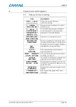
FW V:    1.00.01 

************* 

Shows the actual firmware  
version at startup. 

**    CAMAG    ** 

* ADC2 SER. NO. * 

Display during initialization of ADC2 
at power up. 

**     ADC2     ** 

SYSTEM READY 

The system was properly initialized 
and is waiting for a development. 

THIS METHOD ? 

METHOD  0-10 

Selection of a stored method. 

THIS FUNCTION ? 

MAN. FUNCTION 

Selection of a manual function. 

WAITING FOR 

SOMETHING 

Device is waiting for closing the door, 

moving the lever down or proper posi-
tioning of the Twin Trough Chamber. 

INIT 

DRIVE 

Initialization of specified drive. 

GO TO 

POSITION 

Lift or spindle drive are moved to 
specified position 

TEMP.      HUMIDITY 

+24.9°C  40.1%RH 

The current temperature and relative 
humidity are shown. 

‘ACTION’ 

’REST TIME’ 

An action is running (for example dry-
ing) and the rest time is shown. 

DEVELOPMENT 

45.3mm     22:45 

Development in process since 22 min 

and 45s. The migration distance is cur-
rently 45.3mm. 

OPERATION 

COMPLETED 

Development has been properly com-
pleted. 

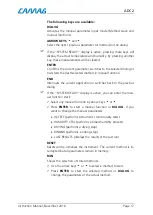
** ERROR 38 ** 

ERROR MESSAGE 

See chapter 6.8, page 26 for error  
messages. 


Summary of Contents for ADC 2

Page 1: ...INSTRUCTION MANUAL ADC 2 ...

Page 2: ... operation 18 5 1 Aborting an application in progress 19 5 2 Resetting the instrument 19 6 Display texts and diagrams 20 6 1 Texts and their meaning 20 6 2 The Normal operation mode dialog 21 6 3 The method stack dialog 22 6 4 The Dialog mode 23 6 5 The Parameters Input dialog 24 6 6 The Manual functions dialog 25 6 7 The Setup dialog 26 6 8 Error messages 27 7 Maintenance and trouble shooting 28 ...

Page 3: ...stays safely protected in the chamber until re moved by the user If used in Stand Alone mode all method parameters are entered via the keypad Ten complete development programs can be saved in nonvolatile memory and started at will without PC control HPTLC plates with a thickness of up to 2 5mm can be used in the ADC2 If using aluminum foils it is mandatory to utilize a special foil holder 115 8363...

Page 4: ...oggles gloves etc if applicable when working with the in strument Before first operation check whether the voltage shown on the instrument matches your local mains voltage The power cord may only be connected to a grounded fused not higher than 16A outlet Do not use extension cords without ground con tact When working with the fluids of the instrument be sure to take the appropriate caution protec...

Page 5: ...er with larger amounts of liquid a service technician has to be called A test of functionality has to be performed in all cases Carry out all safety checks and the preventive maintenance as recommended by the manufacturer in order to assure your per sonal safety and the full functionality of the instrument Have an authorized service specialist perform any service not de scribed by this manual See ...

Page 6: ...011 CCD test plate ADC2 AMD2 115 8357 Plate holder 022 5261 Twin Trough Chamber 941 0006 Saturation pads pack of 25 Respective power cord B 022 8350E Instruction manual English 1 4 Options Part no Description 022 8360 Humidity Control Module 022 8373 Foil holder 1 5 Spare parts Part no Description 022 5261 Twin Trough chamber 022 8370 Saturation pads pack of 100 022 8372 Plate holder 022 8373 Foil...

Page 7: ... of the packing Make sure the shipment is complete Remove the instrument carefully from the package and place it on a table Attention Do not pull out the instrument by holding it at the blue top cover hold the instrument at the bottom when tak ing it out of the package and carrying it around Remove carefully the fixation under the Drying module For shipment the Twin Trough Chamber has been securel...

Page 8: ...y Option Depth 460mm with Humidity Option additional for tubes 250mm Height 520mm Weight 18 5kg Operating temperature The temperature should be within a range of 18 to 30 degrees centigrade and free from significant variations Humidity Humidity and temperature conditions must not cause condensation Atmospheric conditions Adequate ventilation free from acidic alkaline or other gas that may corrode ...

Page 9: ...ric heaters or ovens Do not place the instrument near equipment that generates in tense magnetic fields such as electric welding equipment high frequency furnaces pole transformers etc Protect the instrument from excessive dust Connect the instrument to power lines that are free from sud den changes or voltage fluctuations If you must use power motor driven equipment such as a stir rer or shaker i...

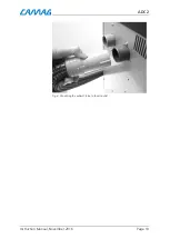
Page 10: ...tion to the PC The CAMAG ADC2 is shipped with a 9 pin RS 232 interface cable for connection to the PC If you wish to use the instrument controlled by a software Connect the cable to the instrument and to a free COM port of the PC to enable data transfer 2 6 Mounting the exhaust tube The shipment contains an exhaust tube which can be slipped on to the black air outlet fig 4 permitting exhaust solve...

Page 11: ...ADC 2 Instruction Manual November 2016 Page 10 Fig 4 Mounting the exhaust tube to the air outlet ...

Page 12: ...age displayed For error mes sages see chapter 6 8 3 2 Checking system functions Switch on the instrument The ADC2 will now show the installed firmware version and perform the following checks and tasks 1 Initializing the drying module 2 Initializing the lift drive If startup was successful the display will show ADC2 SYSTEM READY In this phase only physical blocking of a drive can cause an error If...

Page 13: ...e layer side must be facing the user LAYER side Fig 5 Insert TLC plate in plate holder Important While clamping tight the TLC plate the user should be aware the plate fits the inside stop position and the edges of holder and plate do not overlap Fig 6 Plate clamped in Plate holder Important When clamping the HPTLC plate make sure the plate has hit the stop position 1 and the edges of the holder 2 ...

Page 14: ...t right must be inserted underneath the respective down holders fig 7 Fig 7 Mounting a foil in a foil holder 4 2 Drying module and plate lift To attach the plate or foil holder into the drying module make sure LAYER and substances are facing towards the inside of the drying module fig 8 Fig 8 Fixation of plate holder in drying module ...

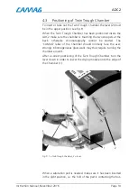
Page 15: ...the back otherwise chromatography cannot be started The CAMAG label of the Chamber should normally face the user strongly inhomogeneous glass walls may thus require turning the chamber around After a correct positioning of the Twin Trough Chamber turn the lever down in order to lower the drying module onto the edge of the Chamber 1 Fig 9 1 Twin Trough Chamber 2 lever When a saturation pad is neede...

Page 16: ...er while the shorter side is lying on the bulge of the chamber fig 10 Fig 10 Positioning of saturation pad 4 4 Developing and preconditioning solvent The inlet reservoirs for developing mobile phase and precondi tioning solvents are located on top of the ADC2 The left inlet is ...

Page 17: ...be 10ml the preconditioning volume 25ml Developing Preconditioning solvent 10ml solvent 25ml Fig 11 Inlet reservoirs 4 5 Display and function of keys Control lamps The control lamps in the display indicate the following status POWER ON this lamp is lit when the instrument is switched on ON LINE this lamp is lit when the instrument is ON LINE with PC and software ...

Page 18: ...r switches back to the previous dialog If the SYSTEM READY display is active you can enter the man ual function stack Select any manual function by arrow keys or Press ENTER to start a manual function or DIALOG if you want to change the manual parameters IQ TEST performs instrument s functionality tests HUMIDITY CTRL performs a timed humidity process DRYING performs a drying step RINSING performs ...

Page 19: ...r local input of parameters Press the RUN key The most recently used method is displayed With the or key you can select another locally stored method Press the DIALOG key to locally change parameters of the se lected method Press the or key to select a parameter group global pa rameters parameters or save method for local input and press ENTER to confirm Now you can step through the parameters of ...

Page 20: ...ld RUN then press END and confirm deleting with ENTER Flow diagrams for these dialogs are depicted in chapter 6 5 1 Aborting an application in progress Procedure Press the END key The development in progress is aborted and if the plate was immersed in solvent a drying process will follow An aborted development cannot be continued 5 2 Resetting the instrument Procedure Press the RESET key This will...

Page 21: ...NG FOR SOMETHING Device is waiting for closing the door moving the lever down or proper posi tioning of the Twin Trough Chamber INIT DRIVE Initialization of specified drive GO TO POSITION Lift or spindle drive are moved to specified position TEMP HUMIDITY 24 9 C 40 1 RH The current temperature and relative humidity are shown ACTION REST TIME An action is running for example dry ing and the rest ti...

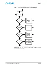
Page 22: ...al operation mode dialog Boxes with two lines on both sides include another diagram shown in the next pages POWER ON SYSTE M RUN END Method stack Repeat last Method Select manual functions Show temperature rel humidity ENTER YES YES YES YES NO NO NO NO UP DOWN ...

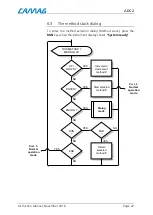
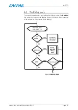
Page 23: ...thod stack press the RUN key when the instrument display shows System ready THIS METHOD METHOD XX ENTER DIALOG RUN END Increment decrement method Start selected method END Delete selected method YES YES YES YES YES YES NO NO NO NO NO Back to Normal operation mode Dialog mode NO UP DOWN Back to Normal operation mode ...

Page 24: ...selection dialog press the DIALOG key when the instrument display shows the name of the method to be edited in the method stack dialog ENTER END Increment decrement dialog type YES YES NO NO NO Enter selected dialog type Data changes YES THIS DIALOG DIALOG TYPE NO UP DOWN YES Back to Method stack ...

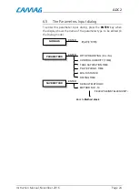
Page 25: ...NTER key when the display shows the name of the parameter type to be edited in the Dialog mode GLOBALS PARAMETERS SAVE METHOD ENTER ENTER CONTROL HUMIDITY TIME TANK SATURATION TIME PLATE PCOND TIME MIG DISTANCE DRYING TIME ENTER DEFAULT METHOD 0 METHOD NO 1 10 Back to Method stack WITH PRE DRYING Yes No FEUCHTE EINSTELLEN ZEIT ...

Page 26: ...election dialog press the END key when the instrument display shows System ready THIS FUNCTION MANUAL FUNCTION ENTER DIALOG END Select function Start selected function YES YES YES YES NO NO NO Back to Normal operation mode NO Increment or decrement drying or hu midity time Back to Normal operation mode UP DOWN ...

Page 27: ...e Setup dialog hold down the DIALOG key wile switching on the instrument DIALOG POWER ON SHOW FIRMWARE VERSION SELECT BAUDRATE SELECT LANGUAGE SELECT LCD CONTRAST PRESS RESET ENTER ENTER ENTER ENTER ENTER All keys except ENTER RESET RESET RESET RESET Back to Normal opera tion mode ...

Page 28: ...ds There is too little solvent available or there are temperature problems e g due to sun light 39 Tolerances of TLC plate or TT Chamber too big 40 The TT Chamber has been moved during development 41 The drying compartment lid has been opened during development 42 The lever has been moved to the up position during de velopment 45 The humidity module is disconnected or there is no module present 47...

Page 29: ...ination procedure below reflects the minimal requirements so keep in mind that the procedure for your instrument has to be adapted according the substances used Decontamination procedure Fill the inlet reservoirs for developing mobile phase and pre conditioning solvents with 25ml of a solvent suitable to dissolve possible impurities most likely Ethanol or Methanol Mount a glass chamber Press end C...

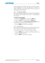
Page 30: ...rast To enter the Setup dialog Hold down the DIALOG key and press the RESET key Release the RESET key then release the DIALOG key The display will now show ADC2 Vx xx xx Setup Mode where x xx xx is the actual firmware version of the ADC2 Press the ENTER key to start the Setup dialog 7 2 1 Set baud rate Start the Setup dialog according to the procedure above The dis play now shows the current baud ...

Page 31: ... Press the ENTER key to accept the current selection and move on to the LCD contrast selection Press the RESET key to quit the setup dialog 7 2 3 Set the LCD contrast Start the user dialog according to the procedure above The dis play now shows the current baud rate Press the ENTER key twice to move on to the LCD contrast se lection display The current contrast setting is displayed Press the or ke...

Page 32: ...t Unlock the fuse holder over the main socket with help of a small screwdriver Press it on both sides of the holder into the recess Now you can pull out the fuse holder Replace the fuse s The label 250 V 1 0 AT slow blow is valid over the full voltage range Push back the fuse box Reconnect the power cord Fig 12 Mains connection switch and fuse holder ...

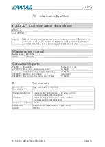
Page 33: ...OQ 12 Months Consumable parts Part No Description Replacement cycle 237 0013 Temperature and humidity sensor 36 Month Salt Solution in humidity control tank 12 Month 022 8370 Saturation pad 100pcs Upon need 022 8375 Filter for humidity control tank 10 pcs 12 Month 8 Technical data Main power connections 100 240 V 50 60 Hz 20 W Drying module drive Stepper motor 1600 steps rev 160 steps 0 1mm Positi...

Page 34: ...t chromatography performed in humid summers or coastal climates can be compared to those performed in dry winters or in highland climates 1 General saturated salt solution The desired humidity is adjusted in the ADC2 by means of a satu rated salt solution not included in shipment Alternatively it is possible to achieve very dry atmospheric conditions if a molecular sieve not included in shipment i...

Page 35: ...ues from Römpp Lexicon Chemistry 9 Edition 2 The solubility values are from Küster Friedrich W Rechentafeln für die chemische Analytik Berlin New York de Gruyter 103 bearb Aufl 1985 Remarks It should be added that heating air of 75 relative humidity from 20 to 21 C reduces the relative humidity by 5 down to 70 A constant temperature is thus necessary for reaching optimal hu midity constancy The sa...

Page 36: ...nnected to the sockets above fig 13 After this the top cover can be attached and fixed with one screw at each side of the module see fig 15 1 Connect the cable to the appropriate connector fig 3 When inserting the components into the gas wash bottle make sure the funnel is sitting on the undissolved salt layer If properly fitted the lid 1 touches the upper edge of the gas wash bottle see fig 14 Fi...

Page 37: ... to connect these hoses correctly because you would fill the ADC2 with salt solution in case of a wrong con nection See fig 14 Fig 15 1 The two sockets directed down on the ventilation valve mount are for exhaust and air supply The exhaust tube has to be slipped onto the black socket fig 15 2 Fig 15 2 Humidity module 1 center hose 2 top cover 3 outside hose 4 exhaust hose Warning Never insert your...

Page 38: ... stirring Add more distilled water in order to reach the 800 mL line that was marked earlier Cool down after 10 minutes to room temperature The fi nal solution should contain about 1 cm of undissolved salt on the bottom to ensure the saturation of the salt solution 3 Sodium chloride rel humidity at 20 C 75 Add 360g NaCl into the humidity control tank Add 500 mL dis tilled water and heat it up to 4...

Page 39: ...umidity cannot be fully reached is due to the adiabatic process and the energy balance during aggregate state changes A good example is shown in the graphics below Fig 16 Measurement of the relative humidity in the ADC2 at start of the humidity con trol Used salt Potassium thiocyanate relative humidity in the lab approx 29 Fig 17 Measurement of the temperature in the ADC2 at start of the humidity ...

Page 40: ...Used plate material Merck HPTLC plates silica gel 60 F 254 Fig 19 shows the values for water absorption for different silica gels from Merck courtesy Merck Humidity larger than 70 is producing irreversible reactions in the binder and should be avoided Fig 19 Humidity adsorption of different silica gel Adsorption Isotherms for Silicagel H2O 20deg C 0 10 20 30 40 50 60 70 80 90 100 0 10 20 30 40 50 ...

Page 41: ......
Reviews: