background image

Getting started 

Instruction manual ATS4, Mar-16 

14


3


Getting started 

3.1


Starting the system 

Switch on the instrument. The ATS4 will now perform the following checks and tasks: 
1. Checking memory for data loss. Parameters (methods) are stored in memory for more 
than 7 days. 
2. Initializing the syringe drive. 
3. Checking gas pressure. In case of low or no pressure an acoustic signal is given and the 
message “Please connect to gas” is displayed. 
4. Initializing the septum punch. 
5. Initializing all other drives. 
6. Finally the application head is moving to the waste position. If start-up was successful 
the display will show:  

**    ATS4    ** 

Instrument ready 

In this phase only physical blocking of a drive can cause an error. If necessary, check if all 
transport locks have been removed and whether there are unknown objects in the 
instrument (for instance below the sample rack). 

3.2


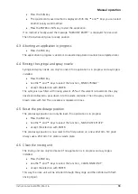
Check syringe and needle type 

Check if the syringe size and needle type is appropriate for your analysis method. 
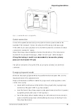
If not, change the syringe and/or needle and adjust the instrument according chapter 2.3 
point “Dosage syringe and needle”. 

3.3


Loading the waste plate 

Prior to application of a sample the application head moves to a position on the waste 
plate in order to pre-dose by contact or spray-on application. These pre-dosage positions 
are 2 mm apart from each other. The waste plate area X: 11 to 189 mm and Y: 11 to 89 
mm is used which results in 3600 pre-dosing positions on each 20x10 plate. Each time 
prior to an application the system checks how many positions are still available. If 
necessary a warning is displayed. When you tell the software that a new waste plate was 
loaded the waste position is reset. 
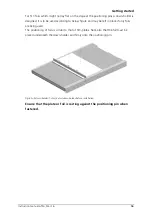
Positioning of the waste plate is achieved by pressing down the left stage. A 20x10 cm 
plate should always be used. 

Summary of Contents for ATS 4

Page 1: ...INSTRUCTION MANUAL AUTOMATIC TLC SAMPLER 4...

Page 2: ...n 9 Rinsing bottles 9 Gas air connection 10 Dosage syringe and needle 10 Mains connection 11 Connection to the PC and installation 12 The user dialog 12 Set baud rate 12 Set display language 13 Set LC...

Page 3: ...Mounting the baffle bridge with septum foil 19 5 Maintenance and troubleshooting 21 5 1 Handling of the HAMILTON syringe 21 5 2 Adjusting the spray gas pressure 21 5 3 Cleaning the spray nozzle 21 5 4...

Page 4: ...nterior parts of the instrument are under AC power Careless and improper use can cause injury Unauthorized manipulations can cause damage This sign indicates on instrument and in this manual that fail...

Page 5: ...efore installation and use the instrument should be acclimated properly Use a damp lint free cloth for cleaning the instrument surface Do not employ aggressive detergents Protect yourself and the inst...

Page 6: ...lectrical and electronic equipment WEEE Directive 2002 96 EC To properly recycle the instrument or parts of it you are requested to send the equipment back to the distributor producer or an adequate c...

Page 7: ...yringe needle for contact application red 695 0065 Replacement seal for syringe needle 695 0046 47 Pkg of 5 695 0061 Replacement piston for 10 L syringe 695 0062 Replacement piston for 25 L syringe 69...

Page 8: ...and lift the instrument up carefully Never try to pull or lift the instrument by means of the transparent cover The cover is not connected with the instrument and will break Do not switch on power bef...

Page 9: ...e from acidic alkaline or other gas that may corrode metal or painted surfaces must be secured Other requirements Do not place the instrument in a location where the temperature undergoes significant...

Page 10: ...uirements exist before installing the instrument Power supply and ground Line voltage 85 250VAC see rating plate on instrument Frequency 47 63 Hz Power capacity 60 VA A grounded outlet should be withi...

Page 11: ...pressure to 6 8 bar 87 115 psi The right air connection is the outlet of the vacuum pump and does not need to be connected Dosage syringe and needle Determine the proper syringe needle for the specifi...

Page 12: ...e is correctly in place After mounting the syringe the syringe volume and the needle type must be entered into the instrument Procedure Press the DIALOG key on the instrument and choose with the keys...

Page 13: ...dialog you can select the communication Baud rate between the instrument and the PC the LCD language and contrast To enter the user dialog Hold down the DIALOG key and press the RESET key Release the...

Page 14: ...e setting Press the ENTER key to accept the current setting and move on to the LCD contrast selection Press the RESET key to quit the user dialog Set LCD contrast Start the user dialog according to th...

Page 15: ...objects in the instrument for instance below the sample rack 3 2 Check syringe and needle type Check if the syringe size and needle type is appropriate for your analysis method If not change the syri...

Page 16: ...t it touches the rear stage ledge and the positioning pin 4 in the middle of the stage Flip up the front stage ledge 2 and move the plate lift lever 1 back to the front Guide the lever with your hand...

Page 17: ...o below figure and may be left in place if only foils are being used The positioning of foils is similar to that of TLC plates Note also that the foil must be placed underneath the down holder and fir...

Page 18: ...rrupts the current application Starts the manual operations dialog to rinse the syringe reset the waste position or clean the rinsing container and spray nozzle RESET Resets and re initializes the ins...

Page 19: ...ection with ENTER The syringe is now filled with rinsing solvent 25 of this solvent is dosed into the spray nozzle and allowed to pour down into the waste container Then the spray nozzle is blown clea...

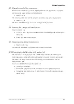
Page 20: ...d the type of the needle Accept your selection with ENTER 4 9 Stopping or resetting the instrument Press the RESET key This will abort all activities in progress and re initialize the instrument 4 10M...

Page 21: ...septum holder 5 attachment screws Position the new baffle bridge with septum foil and attach it with the two screws 5 Insert a septum foil 3 with the Teflon layer face down into the groove of the baff...

Page 22: ...bodies are exchangeable CAMAG recommends exchanging those parts regularly Check the CAMAG Maintenance Data Sheet for information of replacement cycles 5 2 Adjusting the spray gas pressure Spray gas f...

Page 23: ...ply samples from open vials use the optional baffle bridge with septum foil CAMAG part number 022 7460 see Fig 9 The septum foil CAMAG part number 022 7462 is inserted with the Teflon layer face down...

Page 24: ...wer cord Fig 10 Fuse holders 5 7 Troubleshooting During the filling of the syringe bubbles are visible The connection between syringe and needle is not tight Action check connection and tighten it The...

Page 25: ...ght Action Check lid and tighten it No syringe present Action Insert syringe and attach tubing Vacuum pump or valve for emptying waste container is defective Action Request service for vacuum pump or...

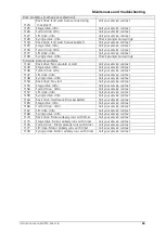
Page 26: ...ontact 220 Rack drive Movement over position limit was requested and aborted by low level driver Call your service contact 221 Stage drive Movement over position limit was requested and aborted by low...

Page 27: ...tto Call your service contact 1147 Lift drive ditto Call your service contact 1148 Syringe drive ditto Call your service contact 1154 Rack drive No start Call your service contact 1155 Stage drive dit...

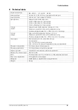
Page 28: ...mm steps X drive stage Step motor 3200 steps rev 8 steps 0 1 mm Maximum speed 200 mm s with acceleration ramp Positions programmable 5 0 195 0 mm in 0 1 mm steps Gas supply External pressure 4 5 6 bar...

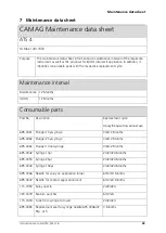
Page 29: ...sumable parts Part No Description Replacement cycle Heavy frequent occasional use 695 0061 Plunger 10 l syringe 3 6 12 Months 695 0062 Plunger 25 l syringe 3 6 12 Months 695 0063 Plunger 100 l syringe...

Page 30: ...61 467 34 34 Fax 41 61 461 07 02 E Mail info camag com CAMAG Germany Bismarckstra e 27 29 D 12169 Berlin Telephone 49 30 516 55 50 Fax 49 30 795 70 73 E Mail infoberlin camag com CAMAG Scientific Inc...

Page 31: ......
Page 32: ..._____________________________________________________________ __________________________________________________________________________________ _______________________________________________________...

Page 33: ..._____________________________________________________________ __________________________________________________________________________________ _______________________________________________________...

Reviews: