Introduction
Instruction Manual, Sep-18
5
1.3
Fluidic principle
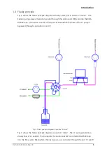
Fig. 2 shows the fluidic principle diagram with loop valve (V2) in position “Elution”. The
Elution pump presses the elution solvent through the ambos and DBS card into the DBS-
MS500 loop (connection 3 and 8 of loop valve). Meanwhile the flow of the LC pump is
bypassed (through connection 4 and 7).
Fig. 2 Fluidic principle diagram in position “Elution”
Fig. 3 shows the fluidic principle diagram in position “Inline”. The LC pump generates a
steady flow of LC solvent. This transports the elution solvent from the DBS-MS500 loop
into the MS system. Meanwhile, the rinsing pump is connected through the port 10 and 9
Summary of Contents for DBS-MS 500
Page 1: ...INSTRUCTION MANUAL DBS MS 500...
Page 40: ......

